If you work with electrical installations long enough, voltage drop becomes one of those topics you stop treating as “just theory.” In real projects, it affects how equipment starts, how efficiently it runs, and whether the load sees the voltage it was actually designed for. Students usually meet voltage drop first in textbooks. Site engineers and electricians meet it when a cable run becomes longer than expected and the equipment at the far end does not behave quite right.
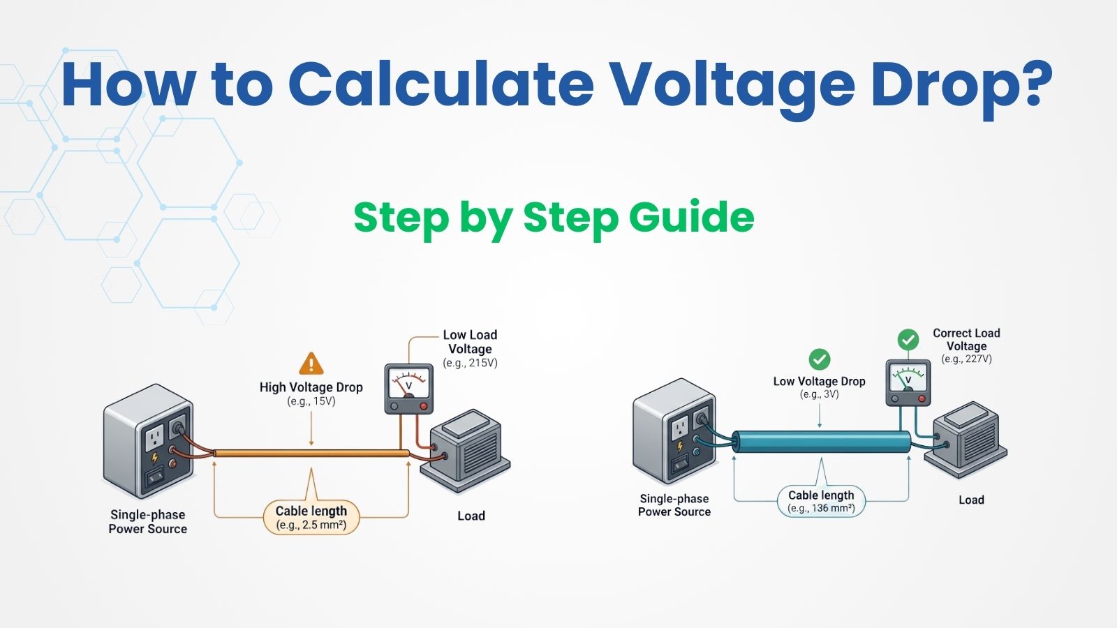
Single-phase voltage drop matters because every conductor has resistance. When current flows through that conductor, some voltage is lost along the way. That lost voltage is what we call voltage drop. In simple terms, the source may be delivering 230 V or 240 V, but the equipment at the far end may receive less because the cable itself is consuming part of the voltage. Good design tries to keep that loss within acceptable limits so performance does not suffer.
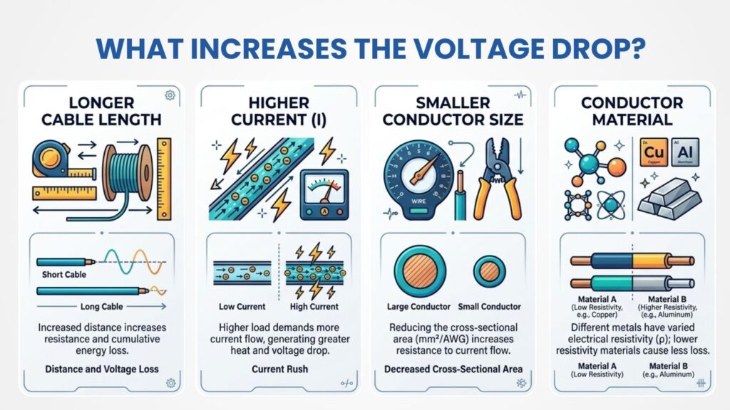
From an engineering point of view, voltage drop becomes more important when the current is high, cable length is long, conductor size is small, or the cable material has higher resistance. That is why a circuit that looks fine on paper from an ampacity perspective may still be poor from a voltage-drop perspective. In practice, you always check both. A cable can be thermally safe and still be a bad choice if the voltage at the load falls too much.
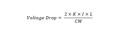
Let us start with the formula used for a single-phase circuit. A commonly used field formula is:
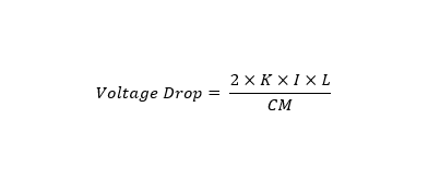
where VD is the voltage drop in volts, K is the resistivity constant of the conductor material, I is the current in amperes, L is the one-way length of the circuit, and CM or CMA is the conductor area in circular mils. For copper, a commonly used K value is about 12.9. For single-phase circuits, the factor of 2 appears because the current travels out through one conductor and returns through the other, so the total path must be accounted for.
That last point is where many beginners make their first mistake. In the formula above, L is the one-way distance, not the full loop length. The factor of 2 already accounts for the outgoing and return path. If you mistakenly double the length yourself and still keep the factor of 2 in the equation, your answer will be too high. This is one of the most common errors I see when students first practice voltage-drop calculations.
Now, let us break the full process into a practical step-by-step method.
Step 1: Gather the basic circuit data
Before you calculate anything, collect the circuit voltage, load current, conductor material, conductor size, and one-way cable length. You also need to confirm that the system is actually single-phase, because the formula for three-phase circuits is different. In the field, this sounds obvious, but many errors happen because somebody uses a three-phase formula on a single-phase problem or vice versa.
In a basic design exercise, you might be given values like a 120 V or 230 V supply, 20 A load current, a copper conductor, and a cable run of 100 feet. If you are working in NEC-style examples, you will often use AWG conductor sizes and circular mil area. If you are working in IEC-style design, you may use cable resistance values in ohms per kilometer. Both approaches are valid when used correctly.
Step 2: Choose the correct single-phase formula
For a straightforward educational example, the NEC-style formula is excellent because it makes the role of current, length, and conductor size easy to see:
This formula is widely used for single-phase voltage-drop work, and it gives you a clean way to estimate how much voltage will be lost across the conductors. In more advanced AC calculations, engineers may also include resistance, reactance, and power factor, especially for long runs or industrial loads. But for students and many practical branch-circuit examples, the formula above is a solid starting point.
Step 3: Find the conductor constant and area
Once you know the conductor material and size, the next job is to find the right constant and conductor area. For copper conductors, K is commonly taken as 12.9 in the standard single-phase voltage-drop formula. Then you need the conductor’s circular mil area. For example, 10 AWG copper has a circular mil area of 10,380. These values are essential because voltage drop depends strongly on conductor resistance, and conductor size directly affects that resistance. A larger conductor has less resistance and therefore less voltage drop.
Step 4: Substitute the values into the formula
Let us use a worked example that is simple enough for students but still realistic for actual installation work.
Assume you have a 120 V single-phase circuit supplying a 20 A load through 10 AWG copper conductors over a one-way distance of 100 feet. We will use K = 12.9 for copper and CM = 10,380 for 10 AWG.
So the formula becomes:
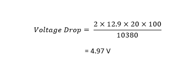
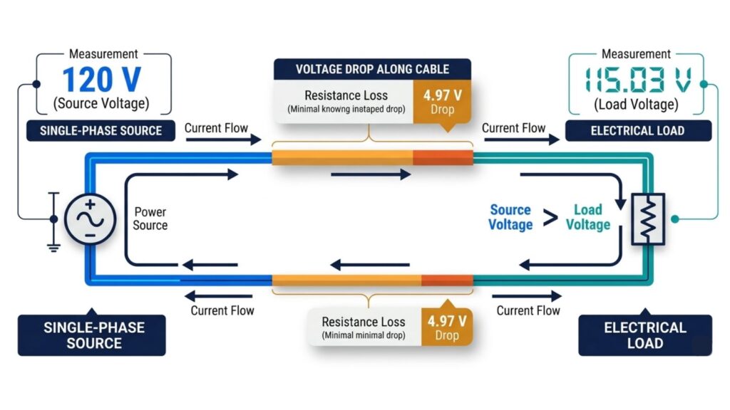
So the voltage drop in this circuit is about 4.97 volts. That is the amount of voltage lost in the conductors before the load receives power. This is the core answer most students are looking for when they first learn the method. The structure of this example follows the same field formula used in standard single-phase voltage-drop references.
Step 5: Calculate the percentage voltage drop
Finding the drop in volts is only half the job. In design practice, what really matters is the percentage voltage drop, because that tells you whether the circuit is acceptable.
The formula is:
Voltage Drop % = (VD / System Voltage) × 100
Using our result:
Voltage Drop % = (4.97 / 120) × 100
Voltage Drop % = 4.14%
So this circuit has a 4.14% voltage drop. That is a useful design number because it immediately tells you whether the cable size is likely acceptable for the intended application.
Step 6: Compare the result with the recommended limits
This is where engineering judgment comes in. Many designers use about 3% maximum voltage drop for a branch circuit and about 5% maximum total voltage drop for the feeder plus branch circuit combined. Under IEC-style guidance, you will also commonly see 3% for lighting circuits and 5% for other power circuits. These are widely used design recommendations intended to preserve proper performance, even though NEC references treat voltage-drop limits as informational guidance rather than a strict mandatory rule in the same way as ampacity requirements.
In our worked example, the answer is 4.14%, which means the circuit is above the commonly recommended 3% branch-circuit target. That does not automatically make the installation unsafe, but it should make you pause. From a design perspective, it suggests the conductor may be undersized if you want good voltage regulation at the load. In real work, the usual next step would be to consider a larger cable size and recalculate until the percentage drop falls to a more comfortable value.
Why does the answer change so much with cable length and size
Voltage drop has a very direct relationship with current and cable length. If the current increases, the drop increases. If the cable gets longer, the drop increases. If you increase the conductor size, the circular mil area goes up, and the voltage drop comes down. This is why long-distance circuits often need much larger conductors than people first expect. The load current may be moderate, but the length pushes the voltage drop beyond a reasonable limit.
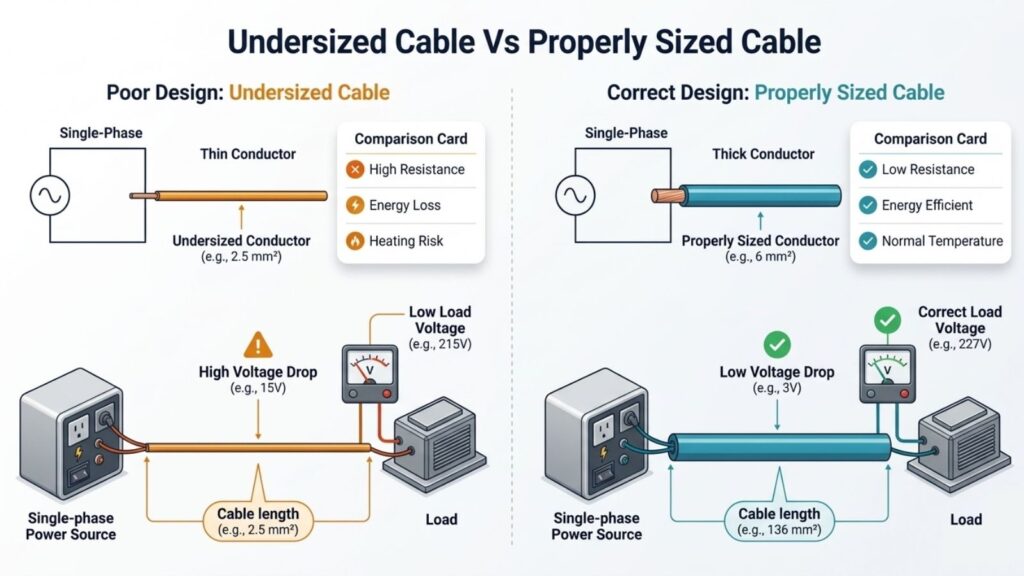
This is also why short residential circuits may work perfectly well with a conductor size that would perform poorly on a detached building, irrigation pump, outdoor lighting run, or remote panel. Same current, very different distance. In engineering design, distance is never an afterthought. It is one of the first things you evaluate when you are checking conductor size.
A simpler way to think about the formula
If the formula feels abstract at first, think of it this way. Current flowing through resistance creates a voltage loss. That idea comes straight from Ohm’s law. The single-phase voltage-drop equation is just a practical form of that principle, adapted to conductor material, wire size, and circuit length. Mike Holt’s treatment of voltage drop also starts from the simple relationship that voltage drop equals current multiplied by resistance. That is the physical idea underneath all the design formulas.
Once students understand that, the formula becomes less intimidating. The factor of 2 is there because the current has an outbound path and a return path. K represents the resistive behavior of the conductor material. CM represents conductor size. Everything in the equation has a physical meaning. You are not just memorizing symbols. You are describing what really happens in the cable.
Common mistakes to avoid
One mistake is using the wrong distance. Always check whether the formula expects one-way length or total loop length. In the standard single-phase formula with the factor of 2 included, the length is one-way. Another mistake is forgetting to convert the voltage drop into a percentage. A drop of 5 V may look small until you realize it is on a 120 V circuit, where it becomes more significant. A third mistake is choosing conductor size only from ampacity tables and never checking voltage drop. That is how you end up with circuits that are technically safe but operationally poor.
A more advanced mistake is ignoring temperature and power factor on long or sensitive circuits. Detailed IEC-style methods include conductor resistance at operating temperature and can include reactance and power factor as well. For many simple branch-circuit examples, the basic formula is enough. But in professional design, especially on longer runs or motor circuits, more detailed calculation methods can matter.
Practical advice from real design work
When I review a single-phase voltage-drop problem, I do not rush to the formula immediately. I first ask whether the result seems likely to be small or large. A light load over a short run with a decent cable size will probably be fine. A heavy load on a long run with a small conductor almost never is. That first engineering instinct helps you catch mistakes before they make it into drawings or installations.
I also recommend that students develop the habit of checking both the numerical voltage drop and the final voltage at the load. If your source is 120 V and your drop is 4.97 V, then the load only sees about 115.03 V. That final number often makes the calculation feel more real. Equipment does not “see percentage.” It sees the actual voltage that arrives at its terminals.
Final thoughts
If you want to calculate single-phase voltage, drop correctly, the process is straightforward once you slow it down and follow the steps. First, gather the circuit data. Then choose the correct formula. Next, find the conductor constants and area. After that, calculate the voltage drop in volts, convert it to a percentage, and compare it with good design recommendations.
For the worked example in this article, a 120 V single-phase circuit carrying 20 A through 10 AWG copper over 100 feet gave a voltage drop of 4.97 V, or 4.14%. That is a solid teaching example because it shows how a circuit can look reasonable at first glance but still exceed the commonly preferred 3% branch-circuit target. Once you understand that, you are no longer just plugging values into a formula. You are making better electrical design decisions.