Transformer voltage problems are common in real electrical installations. A transformer may be correctly sized, correctly connected, and still deliver a secondary voltage that is slightly too low or too high. When this happens, many people immediately suspect a faulty transformer, a bad supply, or an overloaded system. Sometimes those are real causes, but very often the issue is simpler: the transformer tap setting does not match the actual incoming voltage.
A transformer tap changer is provided so the transformer can be adjusted for real site conditions. Utility voltage, industrial feeder voltage, and building distribution voltage are not always exactly equal to the nameplate value. A transformer may be designed for 11 kV on the primary side, but the actual supply may be 10.7 kV or 11.3 kV. A low-voltage transformer may be rated for 480 V on the primary side, but the measured supply may be 470 V or 490 V. Since the secondary voltage depends on the primary voltage and the transformer turns ratio, any change on the primary side appears on the secondary side unless the tap setting is corrected.
This is the main purpose of transformer taps. They are used to match the transformer input voltage with the actual system voltage so the secondary output voltage remains close to the intended value. NEMA guidance for dry-type transformers explains that primary taps are used to match transformer input voltage with system voltage to maintain proper output voltage on the secondary, with common arrangements using 2.5% or 5% tap steps.
In simple words, tap changers are not mysterious. They are practical voltage correction tools. But they must be understood correctly, because choosing the wrong tap can make the voltage problem worse.
What Is a Transformer Tap Changer?
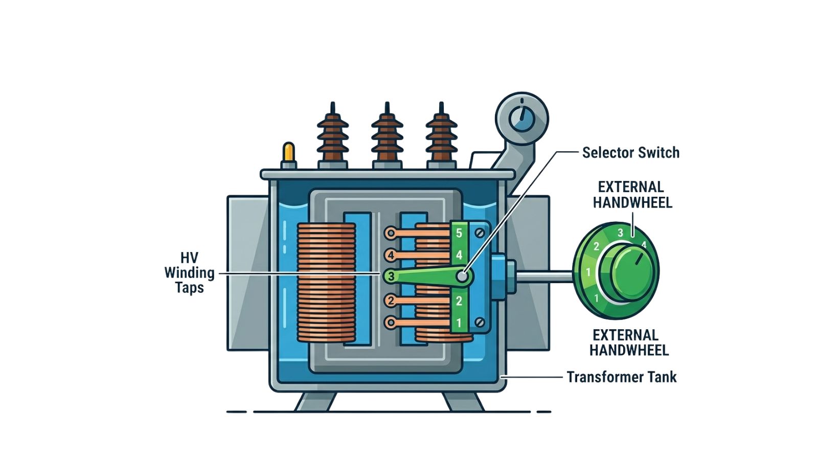
A transformer tap changer is a device or connection arrangement that changes the effective number of turns in one transformer winding. By changing the number of active turns, the transformer ratio changes slightly. Since the transformer ratio controls the relationship between primary and secondary voltage, changing the tap position changes the secondary voltage.
Most distribution and dry-type transformers have taps on the high-voltage winding. This is common because the high-voltage winding carries lower current than the low-voltage winding, making tap construction more practical. However, the exact design depends on the transformer manufacturer, voltage class, and application, so the nameplate and manufacturer diagram should always be checked before making any decision.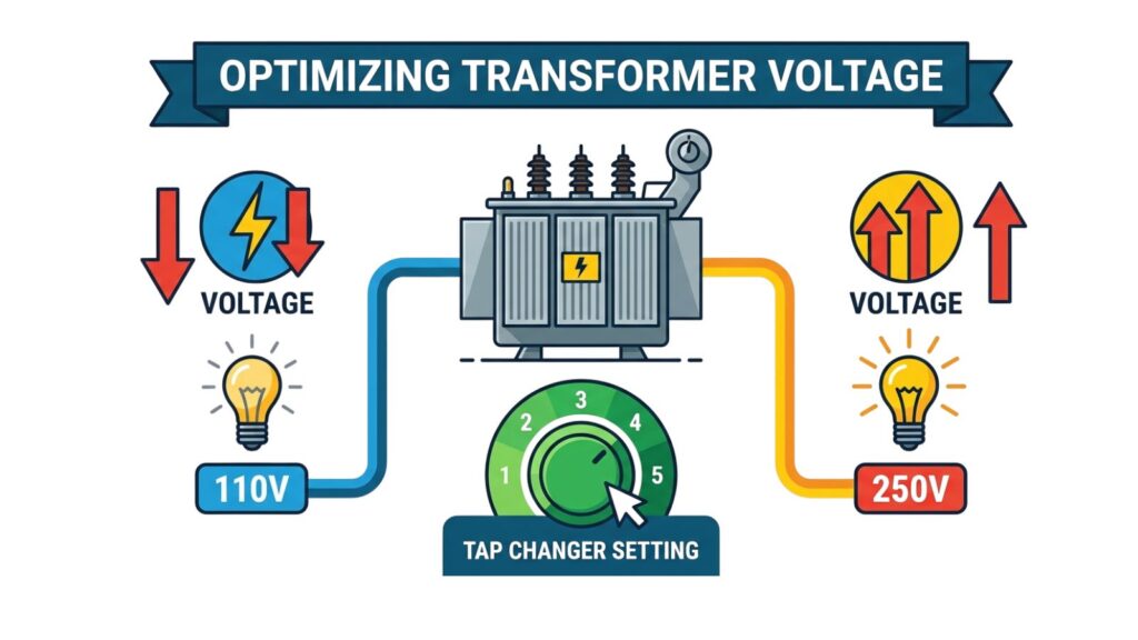
There are two main types of tap changers. The first is the off-circuit tap changer, sometimes called a de-energized tap changer. This type must only be changed when the transformer is isolated, de-energized, locked out, and verified safe. Many building transformers, package substations, and dry-type transformers use this arrangement.
The second type is the on-load tap changer, often called an OLTC. This type can change tap position while the transformer is energized and supplying load. OLTC systems are common in utility, substation, and larger industrial transformers where voltage must be regulated continuously. ABB describes automatic voltage regulation of power transformers with motor-driven on-load tap changers as a typical application for voltage regulation relays.
For most building and facility engineers, the tap changer they encounter is usually an off-circuit tap changer. That means no adjustment should ever be made while the transformer is energized.
Why Transformer Secondary Voltage Becomes Too Low or Too High
The secondary voltage of a transformer is mainly controlled by the primary voltage and the transformer turns ratio. If the transformer is connected on its nominal tap and the primary voltage is exactly nominal, the secondary voltage should be close to the rated value. But real electrical systems are not always ideal.
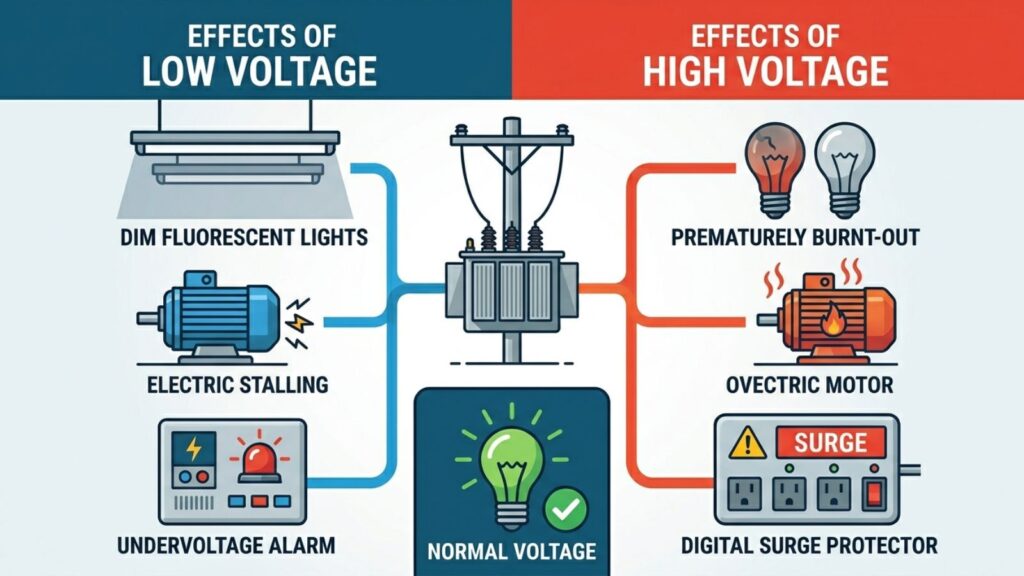
If the incoming primary voltage is lower than expected, the secondary voltage will also become lower. For example, if an 11 kV / 415 V transformer is connected on the 11 kV tap but the actual incoming supply is only 10.5 kV, the secondary voltage will fall below 415 V. The transformer is simply following its ratio.
If the incoming primary voltage is higher than expected, the secondary voltage will also become higher. For example, if a 480 V / 208 V transformer is connected on the 480 V tap but the actual supply is 500 V, the secondary voltage may rise above the desired level.
However, not every low-voltage problem is a tap problem. If the transformer secondary terminal voltage is correct but the voltage at the load is low, the real problem may be voltage drop in cables, long feeder runs, undersized conductors, loose terminations, or high starting current from motors. Tap changers correct transformer ratio mismatch; they do not magically repair poor downstream design.
That is why the first engineering step is always measurement. Measure the primary voltage. Measure the secondary voltage at the transformer terminals. Then measure the voltage at the load. Without those three measurements, it is easy to blame the tap setting when the actual problem is somewhere else.
The Most Important Tap Changer Rule
For the common case where the taps are on the high-voltage winding, the practical rule is:
- When the secondary voltage is too low because the primary supply is too low, select a lower primary tap value.
- When the secondary voltage is too high because the primary supply is too high, select a higher primary tap value.
This rule feels backward to many beginners, so let us explain it carefully.
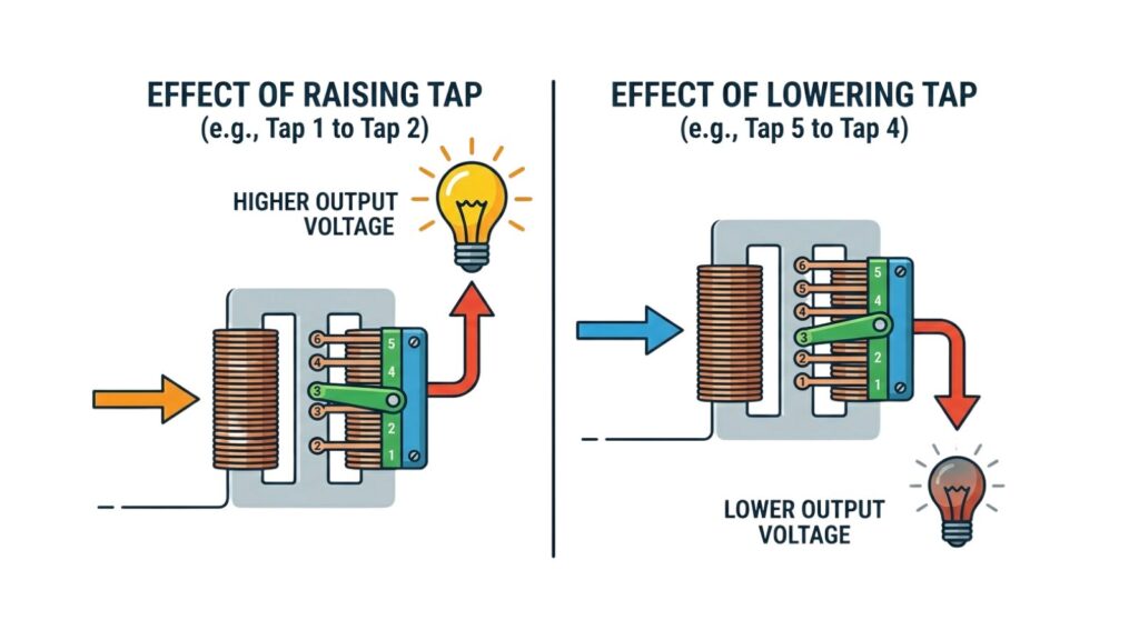
Imagine a transformer designed for 11 kV primary and 415 V secondary. If the actual primary supply is only 10.5 kV but the transformer is still connected on the 11 kV tap, the transformer “expects” more voltage than it is receiving. As a result, the secondary voltage becomes low. To correct this, you choose a lower primary tap, closer to the actual incoming voltage. The transformer ratio then becomes more suitable for the real supply condition, and the secondary voltage rises toward the correct value.
Now imagine the opposite case. If the transformer receives a primary voltage higher than nominal, the secondary voltage will also rise. To reduce the secondary voltage, you choose a higher primary tap value. This adjusts the ratio so the same incoming voltage produces a lower secondary output.
Schneider Electric gives similar practical guidance for transformers where the tap changer is located in the high-voltage winding: when low values appear on the low-voltage terminals, the tap changer should be set for a lower high-voltage value; when excessive voltage appears on the low-voltage terminals, the tap changer should be set for a higher high-voltage value.
This is the heart of tap setting. If you remember only one thing from this article, remember this: with HV-side taps, a lower HV tap usually raises the LV output, and a higher HV tap usually lowers the LV output.
Do Not Use Taps to Create a Different Transformer Rating
A tap changer should not be used as a trick to force a transformer to produce a different voltage from its design rating. This is a serious mistake.
For example, suppose a transformer is designed for 480 V primary and 208Y/120 V secondary. If someone deliberately uses a lower primary tap while still applying full 480 V to the transformer, the secondary voltage may increase above its designed value. That may look useful at first, but it can cause internal heating, insulation stress, and reduced transformer life.
Schneider Electric specifically warns that primary taps on low-voltage transformers are intended to compensate for incoming source voltage that is too high or too low, not to change the secondary voltage to a different level than the transformer was designed for. It also notes that misusing taps this way can increase internal heat and damage transformer windings.
This is an important difference. Correct use means matching the tap to the actual incoming voltage. Incorrect use means abusing the tap to force an output voltage outside the transformer’s intended design.
Step-by-Step Method to Choose the Correct Tap
The safest way to choose a transformer tap is to follow a logical process. First, read the transformer nameplate. Confirm the rated primary voltage, rated secondary voltage, available tap positions, kVA rating, connection type, and whether the taps are on the high-voltage or low-voltage winding.
Next, measure the actual incoming primary voltage. This should be done under normal operating conditions where possible, because voltage may change between light load and heavy load periods. If the site voltage varies significantly during the day, one measurement may not be enough.
Then measure the secondary voltage at the transformer terminals. This is important because it separates transformer output problems from downstream voltage drop problems. If the transformer terminal voltage is already wrong, the tap setting may need review. If the transformer terminal voltage is correct but the load voltage is low, the issue is probably downstream.
After that, compare the actual primary voltage with the available tap values. Choose the tap value closest to the real supply voltage while keeping the secondary voltage within the acceptable range for the connected equipment.
Once the correct tap is identified, isolate the transformer properly. For an off-circuit tap changer, the transformer must be de-energized before adjustment. Follow lockout and tagout procedures, confirm absence of voltage, and only then move the tap links according to the manufacturer diagram.
For three-phase transformers, all phases must be set identically unless the manufacturer provides a very specific instruction otherwise. A mismatch in tap links can create unbalanced voltages and serious equipment problems.
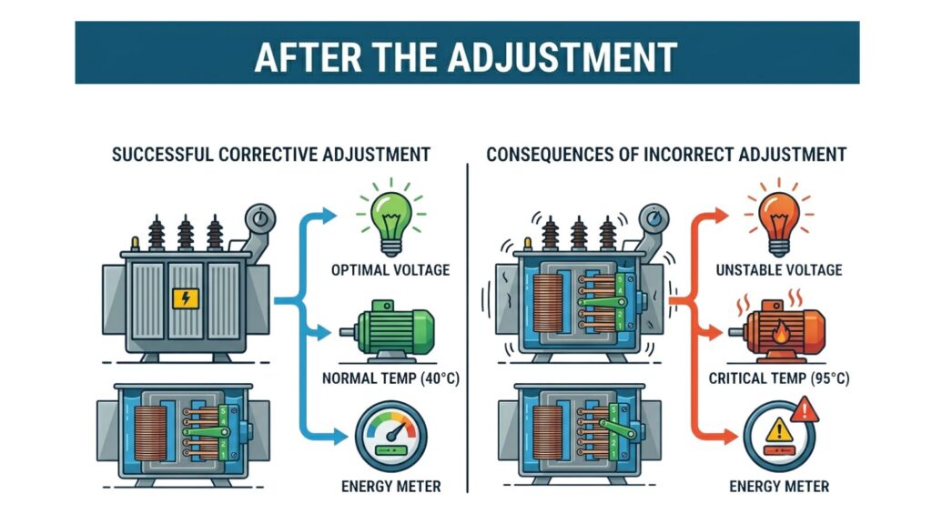
Finally, re-energize the transformer and measure again. Do not assume the correction worked. Confirm the primary voltage, secondary terminal voltage, and load voltage after the adjustment.
Example 1: Correcting Low Secondary Voltage
Assume a transformer is rated 11 kV / 415 V. The available primary taps are:
10.45 kV, 10.725 kV, 11.0 kV, 11.275 kV, and 11.55 kV.
The transformer is currently connected on the 11.0 kV tap. During inspection, the incoming voltage is measured at 10.5 kV. The secondary voltage is lower than expected, around 396 V to 400 V.
In this case, the transformer itself may be healthy. The problem is that the transformer is connected as if it is receiving 11.0 kV, but it is actually receiving only 10.5 kV. The correct action is to select a lower HV tap value, probably 10.45 kV, because that tap is closest to the actual incoming supply.
After changing to the 10.45 kV tap, the transformer ratio better matches the real primary voltage, so the secondary voltage should rise closer to 415 V.
This is a proper tap correction because the tap is being used to compensate for low incoming primary voltage.
Example 2: Correcting High Secondary Voltage
Now assume a transformer is rated 480 V primary and 208Y/120 V secondary. The incoming supply is measured at 495 V. The secondary voltage is also high, and the connected equipment is receiving more voltage than desired.
If the transformer is connected on the 480 V tap, it is operating as though the primary supply is 480 V, but it is actually receiving 495 V. Since the primary is high, the secondary becomes high.
The correct correction is to move to a higher primary tap value if one is available. For example, if the transformer has a 504 V tap, selecting that tap will reduce the secondary voltage closer to the intended output.
Again, this is not being done to create a new output voltage. It is being done to compensate for high incoming source voltage.
Why Tap Percentage Matters
Many transformer taps are provided in percentage steps. Common examples include ±2.5%, ±5%, or several taps above and below nominal. NEMA guidance notes common tap configurations such as two above and four below at 2.5%, two above and below at 2.5%, or one above and below at 5%.
A 2.5% tap change will usually change the secondary voltage by approximately 2.5%, assuming the problem is mainly transformer ratio mismatch. For example, on a 415 V secondary, 2.5% is about 10.4 V. On a 208 V secondary, 2.5% is about 5.2 V.
This means tap changers are not fine laboratory adjustment devices. They adjust voltage in steps. If the voltage is only slightly outside the desired range, one tap step may be enough. If the voltage is far outside the available tap range, the source supply or system design may need deeper investigation.
Off-Circuit Tap Changers: Safety Comes First
Most small and medium distribution transformers use off-circuit tap changers. This means the tap changer is not designed to interrupt load current or change position while energized.
Trying to change an off-circuit tap while energized is extremely dangerous. It can cause arcing, equipment damage, fire, injury, or death. Tap changing should only be performed by qualified personnel using the correct safety procedure.
Before changing taps, the transformer must be isolated from all sources, locked out, tagged out, and tested for absence of voltage. Stored energy and backfeed possibilities must also be considered. In some installations, the transformer secondary may be backfed from generators, UPS systems, solar inverters, or parallel sources. A proper isolation plan is essential.
On-Load Tap Changers: Automatic Voltage Regulation
On-load tap changers are different. They are designed to adjust voltage while the transformer remains energized. These are commonly used in utility substations, industrial substations, and larger transformers where voltage regulation must happen continuously.
An OLTC normally works with a voltage regulator relay or controller. The controller measures voltage, compares it with a target setpoint, waits for a time delay, and then commands the tap changer to raise or lower the voltage if the voltage remains outside the allowed band.
Important OLTC settings include voltage setpoint, bandwidth, time delay, tap limits, and line drop compensation. The setpoint is the desired regulated voltage. The bandwidth prevents unnecessary tap operations for very small voltage changes. The time delay prevents the tap changer from reacting to short voltage dips or temporary disturbances. Line drop compensation can be used when the controlled voltage should represent the voltage at a distant load point rather than only the transformer terminals.
If these settings are poorly selected, the tap changer may operate too frequently, fail to maintain good voltage, or create voltage instability. For this reason, OLTC settings should be reviewed carefully by experienced protection, control, or power system engineers.
When Changing Taps Will Not Fix the Problem
A transformer tap changer is useful, but it is not a cure for every voltage issue.
If voltage is correct at the transformer secondary terminals but low at the load, changing taps may raise the transformer output but it does not remove the cause of the voltage drop. The better solution may be larger conductors, shorter cable routes, better joints, reduced load current, or improved feeder design.
If voltage becomes low only during motor starting, the problem may be starting current, transformer impedance, generator capacity, or feeder impedance. A tap change may improve steady-state voltage but may not solve the starting dip.
If only one phase has abnormal voltage, the issue may be phase imbalance, a loose connection, damaged winding, blown fuse, or incorrect connection. Changing all taps together will not fix a single-phase fault.
If voltage varies widely throughout the day, a fixed off-circuit tap may only provide a compromise. In that case, utility-side regulation, voltage regulators, capacitor banks, OLTC transformers, or feeder improvements may be needed.
Practical Field Tips
Always measure before changing taps. Guessing is risky because a wrong tap change can push voltage further away from the correct value.
Always identify whether the tap values refer to the primary side or secondary side. Most taps are on the high-voltage winding, but never assume this without checking the nameplate.
Always use the actual tap diagram supplied with the transformer. Position numbers alone can be confusing. Tap position 1 may not always mean the highest voltage or lowest voltage across all designs.
Always consider load conditions. A transformer that looks correct at no load may behave differently under heavy load because winding impedance causes voltage regulation effects.
Always check downstream voltage drop separately. If the transformer output is correct but the load voltage is poor, the tap changer is probably not the real solution.
Final Takeaway
Transformer tap changer settings are easier to understand when you focus on their real purpose. A tap changer is used to correct the transformer ratio so the secondary voltage stays near its intended value when the incoming primary voltage is slightly high or low.
For the common case where taps are on the high-voltage winding, low secondary voltage caused by low primary voltage is usually corrected by selecting a lower primary tap value. High secondary voltage caused by high primary voltage is usually corrected by selecting a higher primary tap value.
The correct tap should always be chosen from the transformer nameplate and manufacturer diagram, not from memory or guesswork. Taps should be used to compensate for actual source voltage variation, not to force a transformer to produce a voltage it was not designed to deliver.
Used correctly, tap changers are simple and powerful tools. Used incorrectly, they can create overheating, poor voltage regulation, equipment damage, and safety risks. The professional approach is always the same: measure first, diagnose the cause, choose the correct tap, follow safety procedures, and verify the result.
FAQ
What does a transformer tap changer do?
A transformer tap changer adjusts the effective turns ratio of the transformer. This allows the secondary voltage to be corrected when the incoming primary voltage is slightly higher or lower than the transformer’s rated primary voltage.
Are transformer taps usually on the primary or secondary side?
In many distribution and dry-type transformers, taps are commonly placed on the high-voltage or primary winding. However, this should always be confirmed from the transformer nameplate and manufacturer wiring diagram.
If the secondary voltage is low, which tap should I use?
If the taps are on the high-voltage winding and the low secondary voltage is caused by low primary voltage, you usually select a lower primary tap value. This helps raise the secondary voltage back toward the rated value.
If the secondary voltage is too high, which tap should I use?
If the taps are on the high-voltage winding and the primary supply is higher than nominal, you usually select a higher primary tap value. This helps reduce the secondary voltage.
Can I change transformer taps while the transformer is energized?
Only an on-load tap changer is designed to change taps while energized. Off-circuit or de-energized tap changers must only be adjusted after the transformer has been isolated, locked out, and verified de-energized.
How much does one tap step change the voltage?
Many transformers use 2.5% or 5% tap steps. A 2.5% tap step changes the secondary voltage by approximately 2.5%, although the actual measured result also depends on load and system conditions.
Can tap changing fix voltage drop in long cables?
Not directly. If the voltage is correct at the transformer terminals but low at the load, the issue is likely cable voltage drop. In that case, conductor size, cable length, load current, and connections should be checked.
Can transformer taps be used to boost voltage above the rated secondary voltage?
No. Taps should not be used to force a transformer to produce a secondary voltage beyond its intended design. Doing so can increase heating and reduce transformer life.
Why are all three phases adjusted together?
In a three-phase transformer, all phases must normally have the same tap setting to maintain balanced phase voltages. Unequal tap settings can cause voltage imbalance and equipment problems.
What should be checked after changing taps?
After changing taps, measure the primary voltage, secondary terminal voltage, and load voltage. Also check phase balance and confirm that the transformer is operating normally under load.