Ohm’s Law is one of the most important ideas in electrical and electronics engineering. It looks simple at first, just one equation, but it appears everywhere: in basic DC circuits, in sensor interfacing, in power calculations, in troubleshooting, and even in the first steps of understanding more advanced topics like network analysis and electronics. If you learn Ohm’s Law properly, you gain a reliable mental model for how circuits behave, not just a formula to memorize for exams.
This guide explains Ohm’s Law for electrical and electronics engineering in a clear, student-friendly way. You will learn the Ohm’s Law formula, the relationship between voltage, current, and resistance, how to apply Ohm’s Law to real circuit problems, and the limitations of Ohm’s Law so you know when it does not apply directly. The goal is simple: by the end, you should feel confident solving typical problems and explaining the concept in your own words.
What Is Ohm’s Law?
Ohm’s Law describes the relationship between three basic electrical quantities: voltage, current, and resistance. In the simplest terms, it says that if the resistance of a conductor stays constant, the current through it is proportional to the voltage applied across it.
In engineering practice, this means that for many resistive components, especially standard resistors, the circuit behavior is predictable. Apply more voltage, and the current increases. Increase resistance, and the current decreases for the same voltage. This predictability is the reason Ohm’s Law is used so widely in design and analysis.
Ohm’s Law is not only an academic rule. It is the backbone of many practical decisions: choosing a resistor for an LED, estimating current draw from a battery, calculating the voltage drop on a wire, or checking whether a sensor output is safe for a microcontroller input. Engineers use it constantly because it connects measurable quantities in a direct way.
Ohm’s Law Formula and Its Three Useful Forms
The standard Ohm’s Law equation is: V = I x R
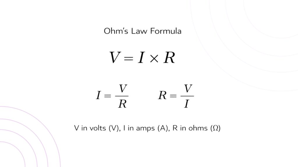
Where V is voltage in volts (V), I is current in amperes (A), and R is resistance in ohms (Ω). This form is usually used when you know current and resistance and want to find voltage.
In real problem solving, you often rearrange it.
If you want current, you use: I = V / R
If you want resistance, you use: R = V / I
These three forms are the same relationship, just expressed differently. Use this calculator to verify your answers. A very common student mistake is using the wrong form or mixing units (for example, using milliamps as if they were amps). If you always write the known values with units first and then select the correct form of the equation, you avoid most errors.
Understanding Voltage, Current, and Resistance Relationship
The voltage, current, and resistance relationship is explained because students want the intuition, not just the math. A good way to build that intuition is to think in cause-and-effect terms.
Voltage is the electrical “push” that encourages charge to move. It does not physically shove electrons like water pressure pushes water, but the analogy is still useful as a mental model. Current is the rate at which charge flows through a conductor. Resistance represents opposition to current flow due to the material, geometry, and conditions of the conductor or component.
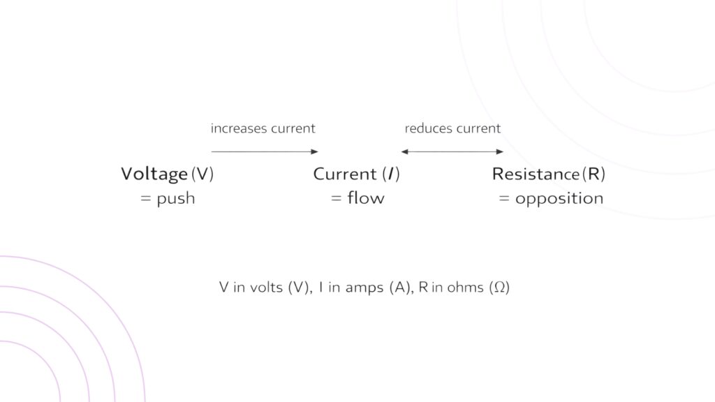
Now notice the relationship: voltage drives current, but resistance controls how much current you get for a given voltage. If resistance is small, even a small voltage can cause a large current. If resistance is large, the same voltage produces a smaller current. That is why resistors are used for current limiting; they deliberately restrict current so components are protected.
This relationship also helps you predict what happens when you change a circuit. If you double the voltage across a resistor and the resistance stays the same, the current doubles. If you double the resistance and keep the voltage constant, the current becomes half. These are simple scaling ideas, but they are extremely valuable in troubleshooting and design.
Ohm’s Law with Simple Examples (The Kind Students Remember)
Let’s start with a straightforward example. Suppose you have a 10 Ω resistor connected to a 5 V DC source.
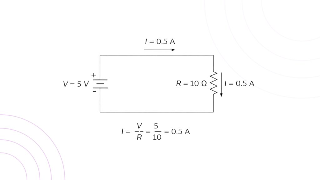
So the current through the resistor is 0.5 A. If you replace the resistor with a 20 Ω resistor while keeping the same 5 V source:
I = 5 / 20 = 0.25A
The current is reduced. This example shows exactly how resistance limits current.
Now consider the reverse case. Imagine your circuit must draw 0.1 A from a 12 V source. What resistance would cause that?
R = V / I
R = 12 / 0.1 = 120Ω
So a 120 Ω resistive load at 12 V draws 0.1 A (ideally). These “reverse problems” are common in engineering because they reflect design decisions: you know what current you want and choose resistance accordingly.
Ohm’s Law Units: Why Engineers Care About Consistency
Ohm’s Law is easy to misuse if units are ignored. Voltage in volts, current in amps, and resistance in ohms must be used consistently for the math to be correct. In electronics, currents are often given in mA and resistances in kΩ. That’s fine, but you must convert properly. For example, 2 mA is 0.002 A. If you accidentally treat 2 mA as 2 A, the result becomes 1000× wrong, which can lead to incorrect design choices. A practical habit is to convert everything into base units before calculating, then convert back for readability. This habit feels slow at first, but it saves time because it prevents mistakes and makes your work easier to verify.
Using Ohm’s Law in Real Circuits (Beyond One Resistor)
Many textbook examples start with a single resistor because it makes the relationship obvious. But in real electrical and electronics engineering, circuits have multiple components. Ohm’s Law still applies; it just needs to be combined with basic circuit rules.
For resistive circuits, you typically use Ohm’s Law together with equivalent resistance concepts. You simplify a network into an equivalent resistance and then use Ohm’s Law to calculate total current or voltage drop.
In practice, engineers often move back and forth between these steps. They simplify where possible, calculate a current, then calculate a voltage drop on a specific resistor, and then adjust the design. This step-by-step approach is how real analysis happens.
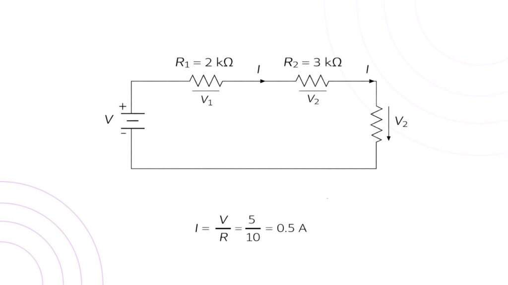
Ohm’s Law in Series Circuits (Clear and Predictable)
A series circuit is one where components are connected end-to-end, giving only one path for current. In series circuits, the same current flows through all components.
The total resistance in a series circuit is simply:
Total Resistance = R1+R2+R3+…
Once you know, you can find the circuit current using Ohm’s Law:
I = V / Total Resistance
Then, the voltage drop across each resistor is:
Vn = I x Rn
This explains a key idea that appears constantly in electronics: voltage division. In a series network, the input voltage is “shared” across the resistors in proportion to their resistance values. This is why voltage divider circuits are so common; they provide simple, predictable output voltages for sensors, references, and biasing.
Ohm’s Law in Parallel Circuits (Same Voltage, Different Currents)
A parallel circuit provides multiple paths for current. In parallel circuits, the voltage across each branch is the same, but the currents can be different depending on branch resistance.
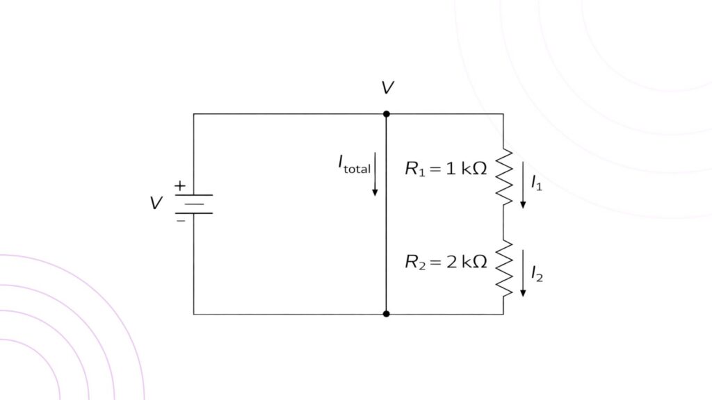
The equivalent resistance of resistors in parallel is given by:
1 / Total Resistance = 1 / R1 + 1 / R2 + 1 / R3 + …
The key practical idea is that adding parallel branches reduces total resistance, increasing total current draw from the source. This is why connecting additional loads in parallel increases the current demand on a power supply.
How to Solve Ohm’s Law Problems (A Reliable Method)
Start by writing down what you know: list voltage, current, and resistance values with units. Next, identify what you need to find. Then choose the correct form of Ohm’s Law and substitute values. Finally, check whether the answer makes sense. For example, if resistance is very high and voltage is small, current should be small. If your result is large, you likely made a unit mistake. Use the Engcal Ohm’s Law calculator to check your answers.
This “sanity check” step is not optional in real engineering. It is how you catch errors before you burn components or misdiagnose faults in a lab.
Power Calculations with Ohm’s Law (The Hidden Superpower)
Ohm’s Law becomes even more useful when combined with power. Electrical power in a DC circuit is:
P = V x I
Power calculations will be briefly discussed in future posts soon.
Limitations of Ohm’s Law (When It Does Not Apply)
A critical part of engineering understanding is knowing the limitations of Ohm’s Law. Ohm’s Law is not a universal rule that works for every component. It applies best to ohmic materials where the relationship between voltage and current is linear, and resistance remains constant for the operating range.
Many real devices are non-ohmic, meaning their V–I relationship is not a straight line. A diode is the classic example. It does not behave like a resistor because current rises rapidly once the forward voltage reaches a threshold. Transistors are also non-linear devices, and their behavior depends on control signals and operating regions.
Temperature is another reason Ohm’s Law may fail in a simple form. The resistance in many materials changes with temperature. A filament lamp, for instance, has a much lower resistance when cold than when hot. If you apply Ohm’s Law using the hot resistance while the lamp is cold, your prediction of current can be very wrong.
So the right engineering mindset is: Ohm’s Law is a powerful tool, but only when the component behaves approximately like a resistor and conditions are stable.
Why Ohm’s Law Does Not Apply to AC Circuits (In the Simple Form)
Students often ask why Ohm’s Law does not apply to AC circuits. The truth is that Ohm’s Law still exists in AC analysis, but it must be written using impedance instead of resistance.
In purely resistive AC circuits, Ohm’s Law works normally. But when you have inductors and capacitors, voltage and current can be out of phase, and opposition to current depends on frequency. In that case, the correct relationship is:
V = I x Z
where Z is impedance. Impedance includes resistance plus reactive components, and it varies with frequency. This is why DC Ohm’s Law feels “broken” in AC circuits, it is not broken, but it is incomplete if you ignore reactance.
This concept is a bridge to more advanced engineering topics: AC circuit analysis, phasors, impedance matching, filters, and power factor.
Ohm’s Law vs Kirchhoff’s Law (How They Work Together)
A common confusion point is Ohm’s Law vs Kirchhoff’s Law. They are different tools used together.
Ohm’s Law relates voltage and current for a component or an equivalent resistance. Kirchhoff’s Laws describe how voltage and current behave in networks. Kirchhoff’s Current Law (KCL) states that currents entering a node equal current leaving. Kirchhoff’s Voltage Law (KVL) states that the sum of voltage rises and drops around a closed loop is zero.
In real circuit analysis, you use KCL and KVL to set up equations for complex circuits, and then use Ohm’s Law to replace currents and voltages in terms of resistances. This combination turns a circuit into a solvable system of equations.
Common Mistakes Students Make in Ohm’s Law Problems
Many students lose marks not because they don’t understand Ohm’s Law, but because of small, repeated mistakes. Unit conversion errors are the biggest one, especially mA vs A and kΩ vs Ω. Another common error is applying Ohm’s Law directly to a network without first finding equivalent resistance. Polarity errors also occur frequently when voltage drops are assumed without defining a reference direction.
A more conceptual mistake is using Ohm’s Law for devices that are not ohmic, such as diodes. In electronics, you often need to understand device characteristics first, then apply Ohm’s Law only where it makes sense (for resistors, wire resistance, and linear regions of some components).
Summary
Ohm’s Law is more than a basic formula. It is a practical framework for understanding and predicting circuit behavior in electrical and electronics engineering. By learning the Ohm’s Law formula, mastering the voltage, current, and resistance relationship, and practicing how to apply it in series and parallel circuits, you gain a skill that supports everything else in circuit analysis. When you also understand the limitations of Ohm’s Law, you avoid common traps and become better prepared for AC circuits and semiconductor electronics.