When you study or design a buck converter, you quickly realize that it does not behave the same way at every load. One of the most important concepts behind this behavior is conduction mode. In this article, you’ll learn what continuous conduction mode (CCM) and discontinuous conduction mode (DCM) mean, how to identify them, and why they matter for ripple, efficiency, and control.
What “Conduction Mode” Means in a Buck Converter?
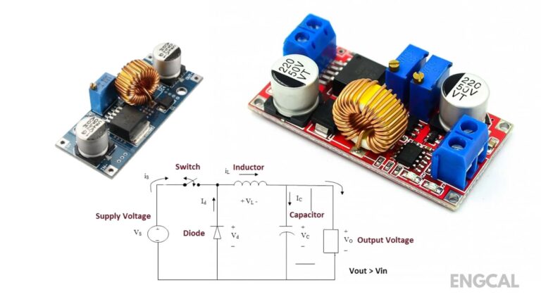
In a buck converter, the inductor is not just a component; it is the energy transfer element. The conduction mode describes what happens to the inductor current during one switching cycle. If the inductor current never falls to zero, the converter is in CCM. If the inductor current reaches zero and stays there for a portion of the cycle, the converter is in DCM.
This difference sounds small, but it changes many practical results, including the voltage relationship, current ripple, and stability.
Continuous Conduction Mode (CCM) in a Buck Converter
A buck converter operates in continuous conduction mode when the inductor current stays above zero throughout the entire switching period. In other words, the inductor is always conducting. CCM usually happens when the load current is moderate or high, because the load keeps pulling current and prevents the inductor current from dropping to zero.
In CCM, the buck converter behavior is easier to predict using the basic duty-cycle idea. Many introductory explanations use the ideal relationship because it fits CCM conditions well (though real converters still include losses).
A key practical benefit of CCM is smoother current flow. Because the current never fully stops, the output ripple tends to be lower for the same component values, and the control loop is often more stable and easier to design. That’s why many DC power supplies are designed so that normal operating conditions remain in CCM.
Discontinuous Conduction Mode (DCM) in a Buck Converter
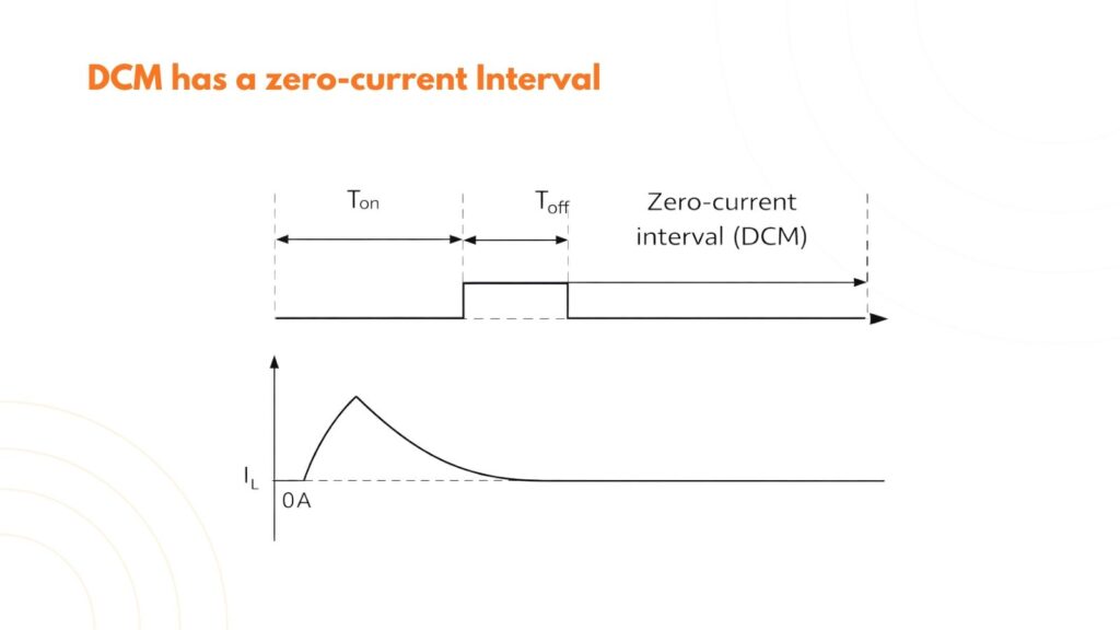
A buck converter operates in discontinuous conduction mode when the inductor current drops to zero during a switching cycle. This often occurs at a light load, when the circuit does not need much energy per cycle. The inductor fully discharges, and for a short interval, there is no inductor current at all.
If you are searching for why a buck converter enters DCM at light load, the reason is straightforward: the energy demand is low, so the inductor does not need to carry current continuously. Many modern converters even encourage DCM or pulse-skipping at light load to improve efficiency.
However, DCM makes the converter’s behavior more complex. The simple duty-cycle voltage relationship does not hold in the same way because the inductor current starts from zero each cycle. In DCM, the output voltage becomes dependent on additional factors such as inductance value, switching frequency, input voltage, and load resistance. This is why two buck converters with the same duty cycle can behave differently in DCM if their component values or loads differ.
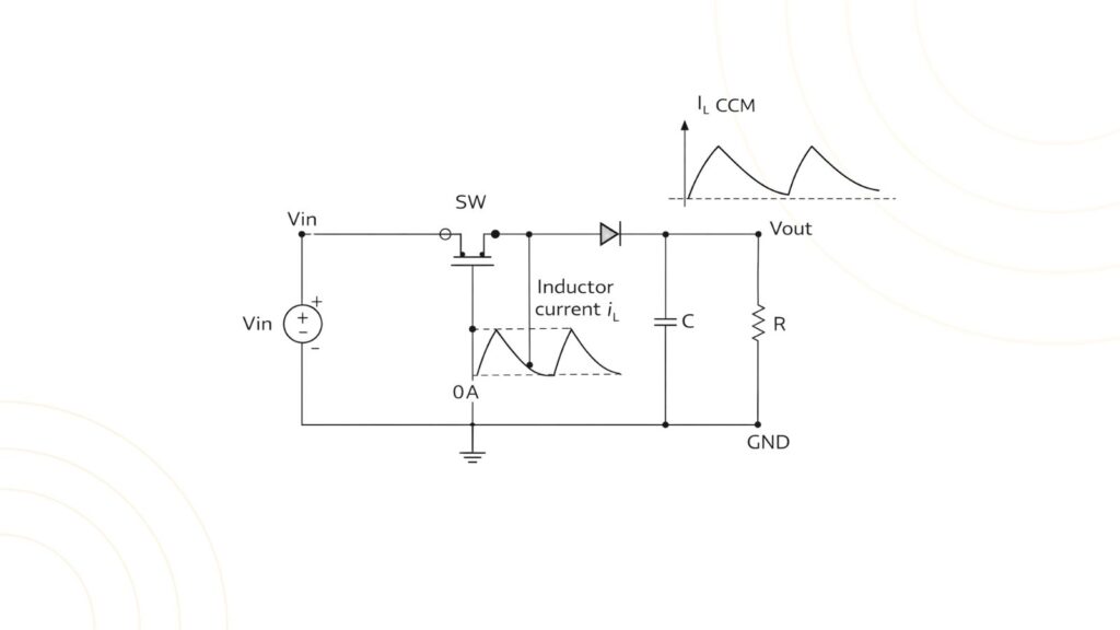
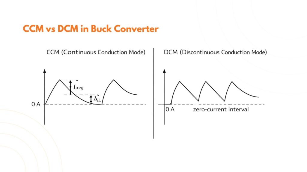
CCM vs DCM Buck Converter Waveforms (What You Would See)
The easiest way to understand CCM vs DCM is to visualize the inductor current waveform. In CCM, the waveform is typically a triangular ripple around an average value, but it never touches zero. In DCM, the waveform rises and falls, touches zero, and then stays flat at zero until the next switching cycle begins.
This is also why DCM can increase ripple and noise. That “flat at zero” interval means energy transfer is not continuous, so the output capacitor has to do more work to maintain a stable voltage.
Key Differences Between CCM and DCM (Practical View)
CCM generally produces lower current ripple for a given inductor value, which often translates to lower output voltage ripple. It also tends to provide more predictable behavior for feedback control. DCM, on the other hand, can show higher ripple and different dynamics, especially when the converter transitions between modes.
Efficiency is more nuanced. At medium and high loads, CCM can be efficient because conduction is smooth and the design can be optimized for low losses. At very light loads, DCM can actually improve efficiency because some control methods reduce switching activity, which lowers switching losses and quiescent power consumption. That is why many IC-based buck converters mention “light-load efficiency” features.
Why CCM vs DCM Matters in Buck Converter Design
If you are designing a converter, conduction mode affects how you choose the inductor and switching frequency. A higher inductance reduces ripple and makes CCM more likely, but it can increase size and cost. A lower inductance increases ripple and pushes the converter toward DCM at lighter loads. Switching frequency also plays a role: higher frequency can reduce required inductance for the same ripple target, but switching losses may increase.
Another important point is mode transition. Some systems operate in CCM at heavy load and shift into DCM at light load automatically. This transition can slightly change ripple, noise, and transient response. If your load includes sensitive analog circuits, you may need extra filtering or a design that stays in CCM across a wider load range.
How to Identify CCM or DCM in a Real Circuit
If you have an oscilloscope and a way to measure inductor current (such as a current probe or a small sense resistor), CCM vs DCM becomes easy to confirm. In CCM, the inductor current waveform never reaches zero. In DCM, it clearly hits zero for a portion of the cycle. If you don’t have a current measurement, you can still suspect DCM when the load current is very low, and ripple/noise increases, or the converter starts skipping pulses.
Summary
The CCM vs DCM buck converter difference comes down to one thing: whether the inductor current ever reaches zero. Continuous conduction mode means current flows through the inductor for the whole cycle, usually at higher loads, giving more predictable behavior and often lower ripple. Discontinuous conduction mode occurs at light load when the inductor fully discharges, making behavior more load-dependent and sometimes noisier, but it can improve light-load efficiency in many modern designs.
Once you understand these modes, you’ll read buck converter datasheets with more confidence and make better decisions about inductors, ripple targets, and performance across load conditions.