Cable Size for 20A 230V 50m: Wire Size Calculation Using 3% Voltage Drop (Worked Example)
If you are searching for a cable size for 20A 230V 50m, you are already thinking like a practical engineer. You probably have a real circuit in mind, like a remote socket run, a small workshop feed, an outdoor supply, or a long branch circuit that needs to “just work” without dim lights or nuisance issues. The reason this exact query is so common is simple. At 230 V, 20 A is not huge, but 50 m is long enough for voltage drop to become the deciding factor, even when the current rating is not.
I have seen many installations where the cable “handles the current,” but the load still behaves poorly. Lights flicker. Motors run hot. Tools feel weak. Contactors chatter. These symptoms often get blamed on the appliance, but the real cause is the cable run. Voltage drop is quiet and sneaky. It usually does not trip a breaker. It just steals performance and reliability.
In this guide, I will show you a clean, repeatable method to select a cable size for a 20 A, 230 V, 50 m run using a 3% voltage drop target. I will also do a full worked example with real numbers, then show you the practical checks that stop mistakes in the field.
Why the 3% voltage drop target matters
A 3% target is widely used as a good engineering rule of thumb for branch circuits that power sensitive loads, lighting, or general receptacles. Even when local standards allow a higher total drop across the whole feeder plus branch, aiming for 3% on a key run gives you margin. That margin becomes valuable when temperature rises, connections age, or load increases later.
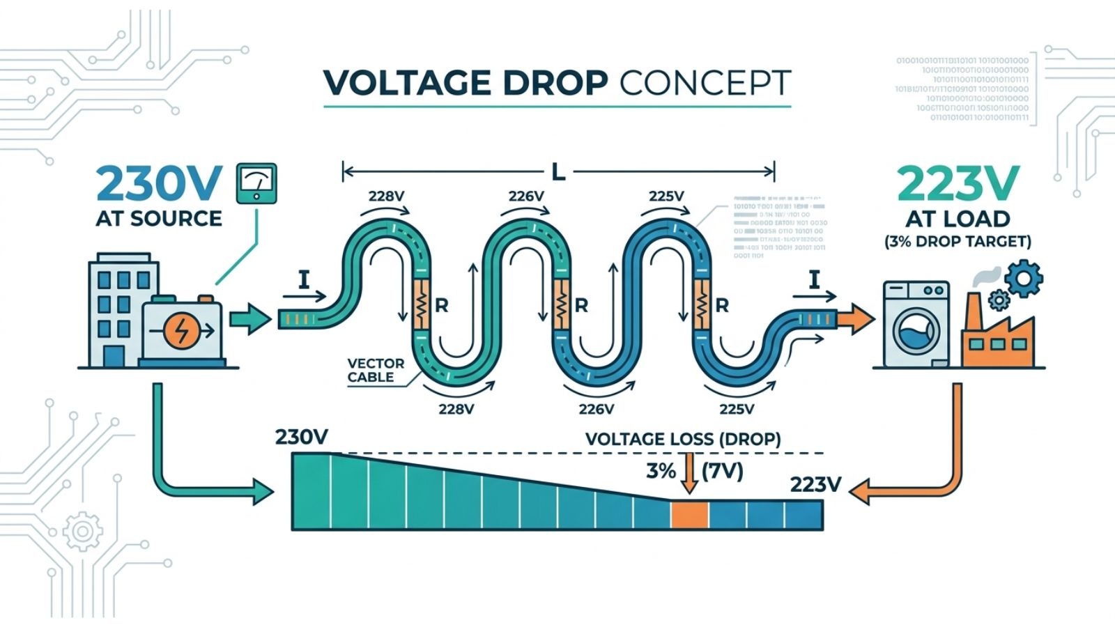
At 230 V, a 3% allowable drop is:
3% of 230 V = 0.03 × 230 = 6.9 V
So if your source is 230 V, the load end should ideally stay above about 223 V under full load. That is the basic design target.
If you allow 5% instead, the allowable drop becomes 11.5 V. That can change the cable size selection. But for many real circuits, 3% is the safer target, especially when the load is not purely resistive.
The voltage drop basics you must get right
Voltage drop in a cable happens because the conductor has impedance. In simple terms, it has resistance, and in AC systems, it also has reactance. Resistance usually dominates for smaller conductors and moderate lengths. Reactance becomes more noticeable as conductors get larger and runs get longer, or when the power factor is low.
For a clean first-pass calculation on typical single-phase runs, you can model the drop using resistance only. That is the approach many quick calculators take, and it is often accurate enough to choose a practical cable size. You should still remember this is an estimate. Real installations add contact resistance, temperature effects, and sometimes meaningful reactance.
The key point that many people miss is the return path.
In a single-phase circuit, current flows out on the line conductor and returns on the neutral conductor. That means the “effective length” for voltage drop is the loop length, not the one-way length. For a 50 m run, the current travels about 50 m out and 50 m back. So the loop length is 100 m.
If you forget that, you can under-size the cable by one full size step, sometimes more.
Step-by-step cable sizing method (the one I actually use)
The workflow is simple if you follow it in the same order every time.
- First, confirm the load current. In this case, it is 20 A.
- Second, confirm the supply voltage and the circuit type. Here it is 230 V, single-phase.
- Third, confirm the one-way cable length. Here it is 50 m. Then convert it to a loop length for voltage drop. In single-phase, the loop length is 2 × 50 m = 100 m.
- Fourth, choose your allowable voltage drop. Here we choose 3%, which is 6.9 V at 230 V.
- Fifth, estimate the conductor resistance based on material and cross-sectional area, then compute the voltage drop and compare it to the limit.
- Finally, after you find a size that passes the voltage drop, check practical constraints like installation method, cable temperature, and future load growth.
Now let’s do it properly with a worked example.
Worked example: cable size for 20A, 230V, 50m using 3% voltage drop Given
Supply voltage: 230 V
Load current: 20 A
One-way length: 50 m
Loop length: 100 m
Allowable voltage drop: 3% = 6.9 V
Conductor material: copper (for the first pass)
Step 1: Use a resistance-based model
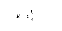
For a conductor, resistance is:
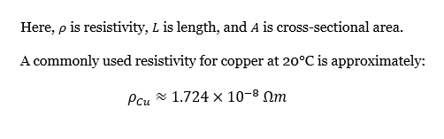
Step 2: Choose candidate cable sizes and test them
Cable sizes are normally selected from standard sizes such as 2.5 mm², 4 mm², 6 mm², 10 mm², and so on. Since the current is only 20 A, many people start at 2.5 mm². Let’s test it.
Remember to convert mm² to m²:
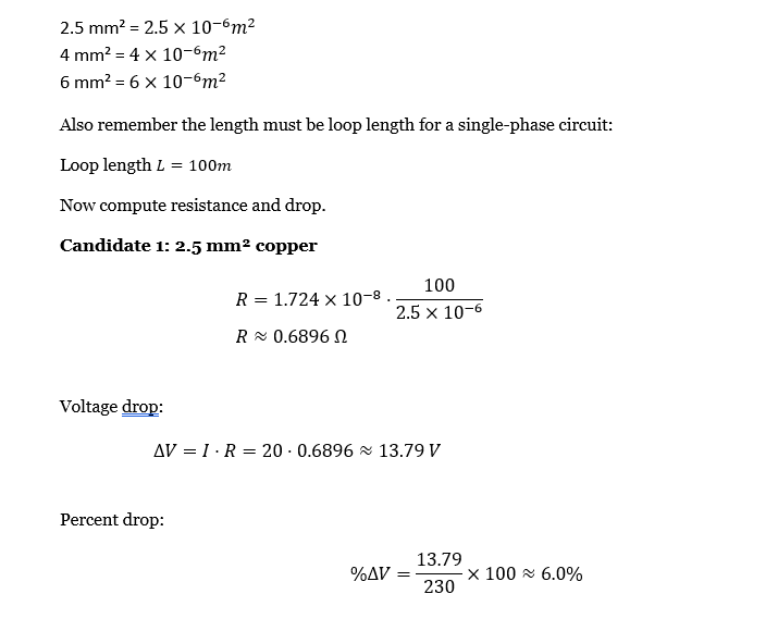
This fails a 3% target. It even exceeds 5% in many cases. For this run length, 2.5 mm² is too small if you are serious about performance.
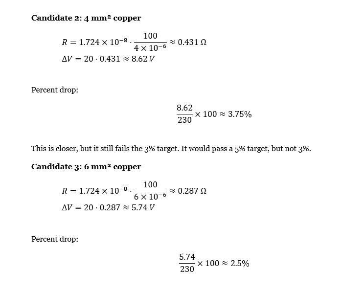
This passes the 3% target with a margin. So, for a 20 A, 230 V, 50 m run, a reasonable first-pass answer is 6 mm² copper if you want to stay around 3% voltage drop.
That is the core result.
What does this result mean in real life?
A 6 mm² copper cable for 20 A might feel “oversized” if you think only in terms of current rating. But voltage drop is a different constraint than ampacity. Ampacity answers “Will the cable overheat?” Voltage drop answers “Will the load receive usable voltage?”
At 50 m, the voltage drop becomes meaningful. You can run a 20 A load on a smaller cable safely from a thermal standpoint, depending on installation conditions, but the load might not behave well. Oversizing the cable reduces voltage drop and improves performance. It also gives margin for future load growth.
If the load is a motor, this matters even more. Many motors draw higher current during starting. A small extra voltage drop can reduce starting torque, causing longer start time and more heating. That is how a “normal” cable choice becomes a reliability issue.
Quick sensitivity check (engineer’s sanity test)
It helps to see how the answer moves when the design target changes.
If you allowed 5% drop instead of 3%, your allowable drop would be 11.5 V. In our calculation, 4 mm² had about 8.62 V drop, which is 3.75%. That would pass 5%. So the cable size can drop from 6 mm² to 4 mm² if your application and standards allow it.
This is why it is important to pick the voltage drop target based on the load type and the quality you want. A strict target costs more cable but reduces nuisance issues. A loose target saves cable but increases the risk of poor performance.
Temperature makes voltage drop worse (and it matters)
Copper resistance increases with temperature. In practical installations, the conductor rarely stays at 20°C. In conduit, in insulation, in hot outdoor locations, or in grouping, the conductor can run much hotter.
A good engineering habit is to treat the 20°C calculation as a best-case. Then apply a realistic margin. If the conductor operates at a higher temperature, its resistance can increase noticeably. That means the voltage drop increases by the same percentage.
This is one of the reasons I like the 6 mm² result for a 3% target. It gives margin. With 4 mm², you were already above 3% at room temperature. Any temperature increase makes it worse.
Copper vs aluminum for the same run
If you use aluminum instead of copper, the resistivity is higher, so the voltage drop is higher for the same cross-sectional area. The design often needs a larger aluminum conductor to achieve the same drop.
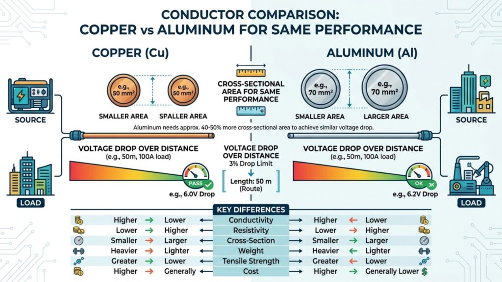
This does not mean aluminum is “bad.” It means you must size it properly and use correct terminations. For long runs where cost matters, aluminum can still be a good solution. But if you are targeting a tight voltage drop, copper usually reaches the target with a smaller cross-section.
If you plan to use aluminum on this exact run, treat 6 mm² copper as a reference point and expect to step up in size for aluminum to achieve a similar drop.
Practical selection rules that prevent costly mistakes
The first rule is to use the loop length for single-phase voltage drop. For a 50 m run, use 100 m in the resistance calculation.
The second rule is to choose a voltage drop target that fits the load. For lighting, electronics, and mixed-use circuits, 3% is a solid design target. For non-critical loads where standards allow it, 5% may be acceptable. For low-voltage DC systems, you often need tighter targets because a small drop is a large percentage.
The third rule is to size for the worst realistic current, not the nameplate fantasy. If you have a load that runs near 20 A continuously, design at 20 A. If it has a significant starting surge or intermittent peaks, consider whether the peak matters for performance. Starting events can expose a weak voltage drop design.
The fourth rule is to treat the calculation as an electrical estimate, not the whole design. Installation method, grouping, ambient temperature, and local codes determine ampacity and protection coordination. Voltage drop sizing does not replace those checks.
Common mistakes I see with “20A, 50m” runs
The most common mistake is using the one-way length instead of the loop length. That error cuts the calculated drop in half, and it pushes people toward cables that look fine on paper but behave poorly in reality.
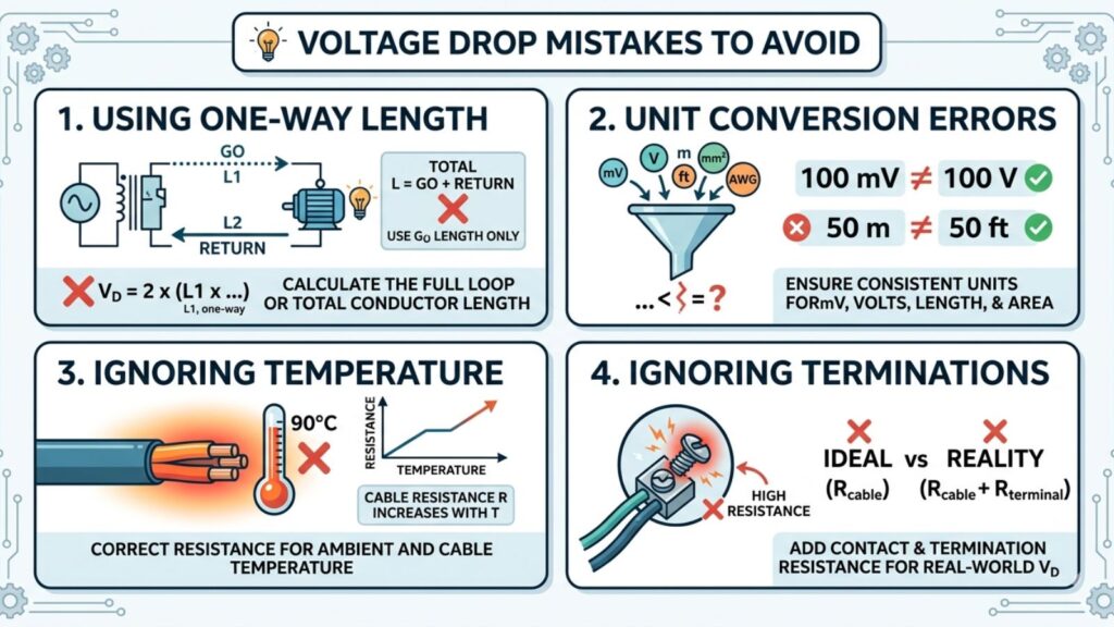
Another common mistake is mixing units. mm² must be converted to m² if you use resistivity formulas. kΩ and Ω mistakes can destroy the result by orders of magnitude. If your answer seems too good to be true, it usually is.
I also see people ignore temperature. They design at 20°C and install in hot conditions, then wonder why the voltage is low at the far end. Temperature and termination quality both matter. A loose termination can add more “extra resistance” than meters of conductor, especially at higher currents.
Finally, many people forget the load type. A resistive heater will tolerate a voltage drop differently than a motor or electronic power supply. Some switch-mode power supplies draw more current when the voltage drops, which can worsen the problem. That can create a loop where voltage drops, current rises, the drop increases further, and the cable runs hotter.
How to use EngCal to speed this up
For day-to-day work, you do not need to calculate resistivity by hand every time. Your Wire Size Calculator is built for exactly this type of query. You enter the supply type, current, length, allowable voltage drop, and material. It returns a suggested conductor size with worked examples that make it easier to trust the result.
A good workflow is to do one manual worked example like the one above. That builds intuition. After that, use the calculator for rapid iteration. You can test “what if we allow 5%” or “what if the run is 70 m” in seconds. Then you can decide whether the additional copper cost is justified.
You can also use the Voltage Drop Calculator when you already know the cable size and want to check the expected drop quickly. That is useful during troubleshooting and when verifying an existing installation.
FAQ
A common question is whether 6 mm² is always required for 20 A at 50 m. The answer is no. It depends on your allowable voltage drop. If you accept 5%, then 4 mm² often becomes acceptable for many cases. But if you want 3% and you want margin for temperature and real-world conditions, 6 mm² is a sensible choice.
Another question is whether increasing the supply voltage solves the problem. Higher voltage reduces current for the same power, and that reduces voltage drop. So yes, using a higher distribution voltage can help. But in most residential and small commercial contexts, you are constrained by the supply voltage you have. In those cases, conductor sizing and load management are your main tools.
People also ask whether it is okay to “just accept” a little extra drop. Sometimes it is. But if the load is a motor, a compressor, or an electronic supply near its limits, an extra drop can create operational issues that are expensive to troubleshoot later. In my experience, spending a bit more on conductor size for long runs often pays back in reliability.
Assumptions and limits
This worked example used a resistance-based model with copper resistivity at 20°C and a single-phase loop length of 100 m. Real cables have slightly different resistance values depending on standard, stranding, and operating temperature. AC reactance and power factor can also influence voltage drop, especially in longer runs and certain cable arrangements. Use this as a strong planning method, then verify with your local standard tables and installation conditions for the final design.