If you are designing or studying power electronics, understanding buck converter efficiency calculation is essential. Efficiency tells you how much of the input power actually reaches the load, and how much is lost as heat inside the converter. A buck converter is popular because it can be very efficient, but the real efficiency depends on the components, switching frequency, and load current. This short guide explains how to calculate buck converter efficiency clearly, with practical examples and design insight.
What Is Buck Converter Efficiency?
Buck converter efficiency is the ratio of output power to input power. In simple terms, it answers this question: “Out of the power I feed into the converter, how much do I get back at the output?” The remaining power becomes losses, usually appearing as heat in the MOSFET, diode (or synchronous MOSFET), inductor, and PCB traces.
Most students search for how to calculate buck converter efficiency because they see an output voltage that looks correct, but the circuit still runs warm. Efficiency explains why that happens.
Buck Converter Efficiency Formula
The standard formula is:
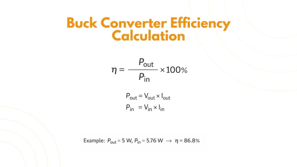
So, a practical form of the buck converter efficiency calculation is:
Step-by-Step Example (Realistic Numbers)
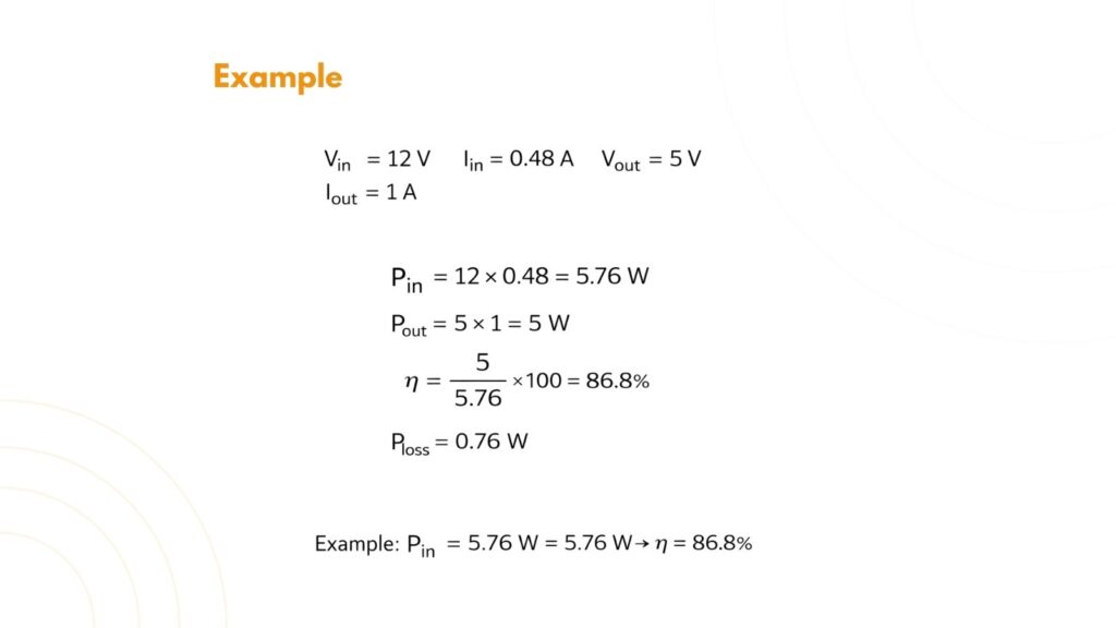
Let’s say you build a buck converter that steps down 12 V to 5 V, powering a load that draws 1 A. You measure the input current as 0.48 A.
Why Buck Converter Efficiency Changes with Load?
A common long-tail question is why the buck converter efficiency is low at light load. The reason is that some losses stay almost constant even when the output power is small. For example, switching the MOSFET requires gate drive power every cycle, and the control IC consumes its own operating current. When the load is light, these “fixed” losses become a bigger percentage of the total.
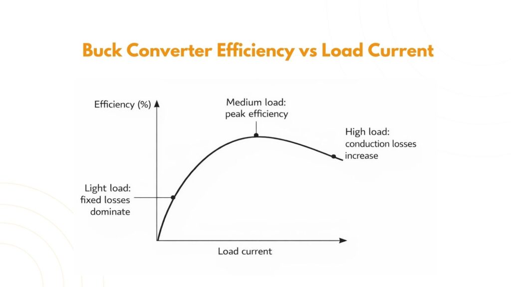
At heavier loads, conduction losses become more important. Resistance in the MOSFET (Rds(on)), inductor DCR, and PCB copper causes power loss proportional to current squared. That’s why efficiency may rise to a peak at moderate load and drop again at high load.
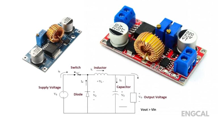
Main Sources of Loss in a Buck Converter
To understand efficiency better, it helps to know where the input power goes. In most designs, losses come from switching and conduction. Switching losses occur during MOSFET transitions because voltage and current overlap briefly. Conduction losses happen because real components are not ideal: MOSFETs have on-resistance, diodes have forward voltage drop, and inductors have winding resistance.
If you are searching for how to improve buck converter efficiency, the general direction is to reduce these losses by choosing a suitable switching frequency, using low-loss components, and ensuring good PCB layout.
Quick Tips to Measure Efficiency Accurately
For accurate results, use stable measurements. Measure input and output voltage at the converter terminals, not at the power supply leads. Use a decent multimeter or power analyzer, and ensure your load current is steady. Even small measurement errors can noticeably affect efficiency, especially at light loads.
Buck converter efficiency calculation is straightforward: compute input power, compute output power, then take the ratio. The deeper value comes from interpreting the number. If efficiency is lower than expected, look at switching losses, conduction losses, and how the converter behaves at your load current. Once you understand these basics, it becomes much easier to design buck converters that run cooler and waste less power.