Ohm’s Law is one of the first tools students use in electrical engineering because it connects voltage, current, and resistance in a simple relationship. In many DC circuit problems, it works perfectly and gives quick answers. But in real electronics, not every component behaves like a fixed resistor. That is why limitations of Ohm’s Law are so common; students often reach a point where they try V=I x R, and the result does not match what they observe in the lab.
The most important idea is this: Ohm’s Law applies to ohmic materials and devices where resistance remains constant for the operating range. When resistance changes with voltage, current, temperature, light, or frequency, the device becomes non-ohmic, and the simple linear relationship breaks down.
What does Ohm’s Law Assume? (The Condition Students Miss)
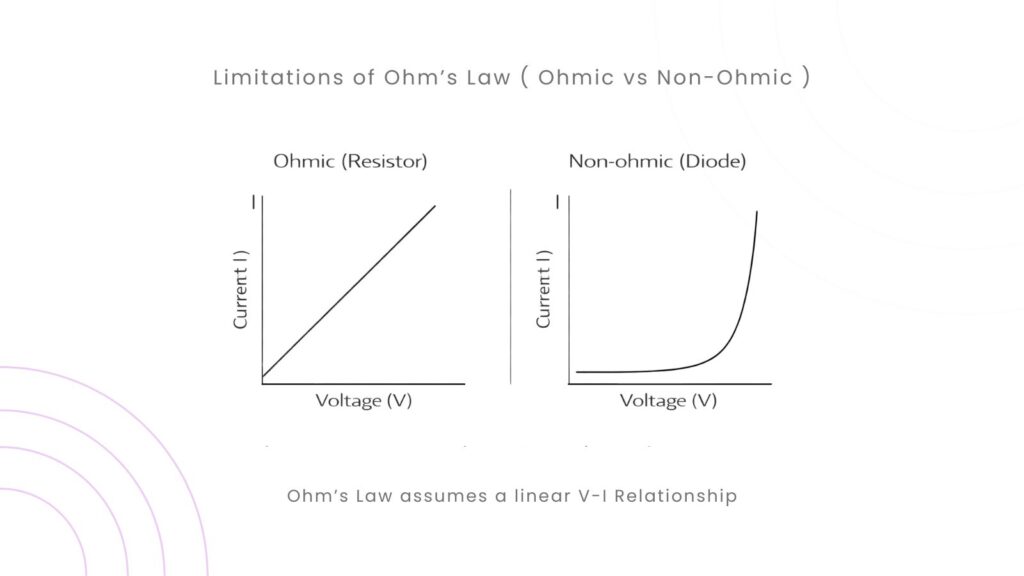
Ohm’s Law does not simply say “voltage equals current times resistance.” It also assumes the resistance is constant while the measurements are taken. In other words, it assumes a linear V–I characteristic. If you plot voltage on the x-axis and current on the y-axis for an ohmic device, you get a straight line through the origin. The slope of that line is the resistance.
This linear behavior is common for many resistors under normal conditions, but it is not universal. Once the device heats up, enters a different operating region, or has a non-linear characteristic, the “constant R” assumption becomes invalid.
Limitation 1: Ohm’s Law Does Not Apply to Non-Ohmic Devices
The first and one of the most important limitations of Ohm’s Law is that it only applies to ohmic devices. That means components whose voltage–current (V–I) relationship is linear. Many electronic components are intentionally non-linear. Their current does not increase proportionally with voltage. A diode is the best-known example. Below a certain forward voltage, a diode conducts very little current. After that point, current rises sharply with small increases in voltage. If you try to model a diode using a constant resistance, you’ll get misleading results.
The same idea applies to transistors, LEDs, and many semiconductor devices. Their behavior depends on internal physics, junction voltage, and operating region. In these cases, Ohm’s Law may still be used for external resistors in the circuit, but it cannot be used to model the device itself as a fixed resistor.
Limitation 2: Resistance Changes with Temperature
Temperature is one of the biggest practical limitations of Ohm’s Law in real circuits. Many materials have a resistance that changes as they heat up. Even normal resistors can drift slightly, but some components change dramatically.
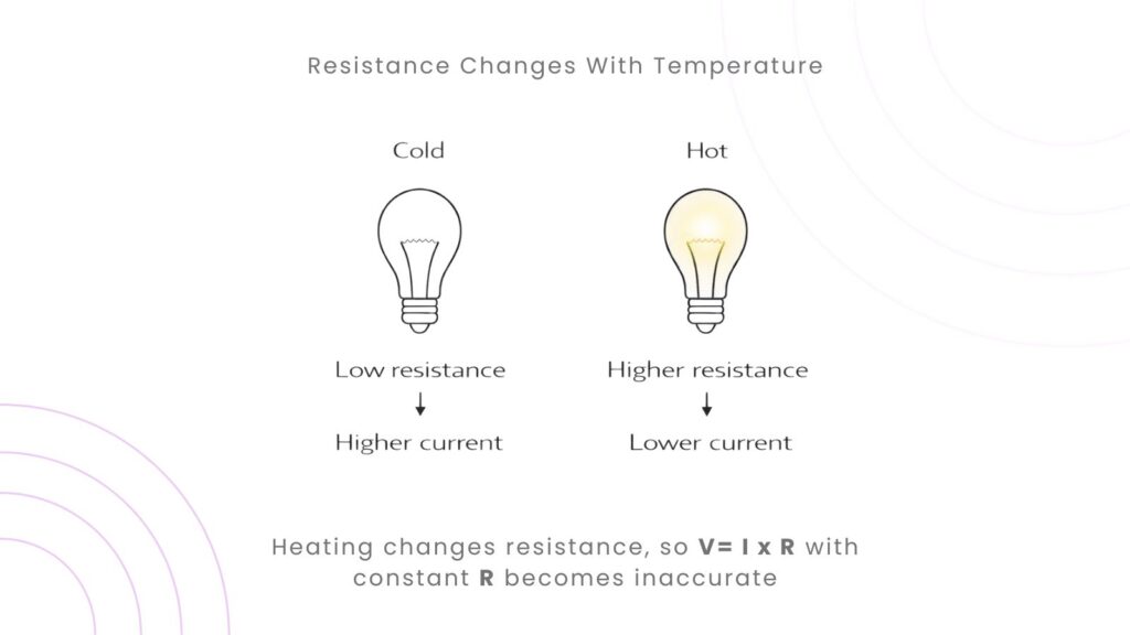
A filament lamp is a classic example. When the filament is cold, its resistance is low, so the initial current is high. As the filament heats up, resistance increases, and the current settles to a lower steady value. If you apply Ohm’s Law using the “hot” resistance to predict the “cold-start” current, your prediction will be wrong.
This is also why engineers care about temperature coefficients and why power resistors are rated for specific conditions. In real designs, resistance is not always a fixed number. It can be a changing property.
Limitation 3: High Electric Fields and Material Nonlinearity
Some materials do not maintain a constant resistance as the applied voltage increases. At high electric fields, conduction mechanisms can change, causing non-linear behavior. This is less common in basic circuits, but it becomes important in insulation materials, gas discharge devices, and high-voltage systems.
For student-level understanding, the takeaway is simple: even if a device looks like a resistor at low voltage, it may not behave like one at higher voltage.
Limitation 4: Ohm’s Law in AC Circuits Needs Impedance, Not Just Resistance
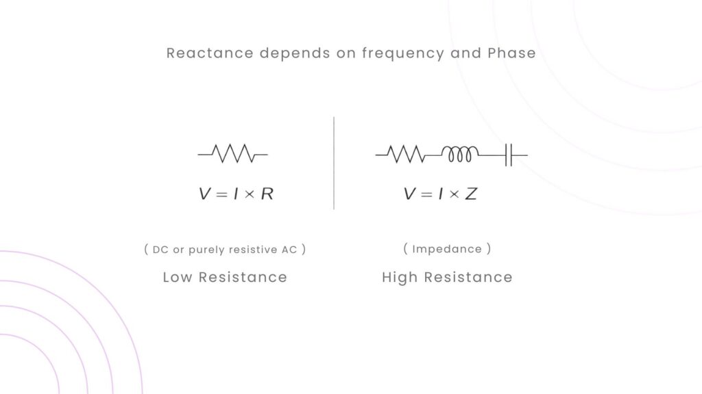
Another major topic is AC. Students often search for why Ohm’s Law does not apply to AC circuits because they try to use it in circuits that contain inductors and capacitors. In AC, resistance is not the only opposition to current. Inductors and capacitors introduce reactance, which depends on frequency and creates phase differences between voltage and current.
In AC analysis, the correct form is:
V = I x Z
Where impedance is, combining resistance and reactance? Ohm’s Law still exists, but it must be written using impedance to represent how AC circuits really behave.
Limitation 5: Ohm’s Law Is Not a Complete Circuit Law
Ohm’s Law describes the relationship across a component (or an equivalent resistance). It does not, by itself, tell you how voltages and currents distribute in a complex network. That’s why you also need Kirchhoff’s Laws. In real circuit analysis, engineers use Kirchhoff’s Current Law and Voltage Law to set up the network equations, and then use Ohm’s Law to relate current and voltage within resistive parts of the circuit.
So if you are trying to solve a multi-loop circuit using only Ohm’s Law without network rules, you will quickly hit limitations.
How to Know When You Should Not Use Ohm’s Law Directly?
A good engineering habit is to ask: “Is the device linear and resistive in this operating range?” If the answer is yes, Ohm’s Law is safe. If the device is a diode, transistor, capacitor, inductor, or temperature-dependent component, then you need a different model.
A simple checklist that helps in exams and labs is to watch for signs of non-ohmic behavior: current rising rapidly after a threshold, heating effects, or frequency-dependent response. These clues tell you that resistance is not constant.
Final Thoughts
The limitations of Ohm’s Law come from its hidden assumption: resistance must remain constant, and the device must behave linearly. Ohm’s Law works well for ohmic resistors under stable conditions, but it does not describe non-linear devices like diodes and transistors; it can fail when temperature changes significantly, and it must be extended to impedance when dealing with AC circuits containing inductors and capacitors.
Once you understand the limitations of Ohm’s law, your circuit analysis becomes more accurate, and your troubleshooting becomes much easier. Because you stop forcing every component to behave like a resistor.