
Many students learn Ohm’s Law early and then feel confused when they start AC circuits. In DC, the relationship looks clean and reliable: voltage, current, and a simple equation link resistance. But in AC, the same approach often produces wrong answers. Especially when inductors and capacitors are involved. That’s why people search for why Ohm’s Law does not apply to AC circuits and the limitations of Ohm’s Law in AC so frequently.
The good news is that the idea behind Ohm’s Law still exists in AC circuits. What changes is the meaning of “opposition to current.” In AC, resistance alone is not enough. You must consider reactance and impedance, and you must account for the phase difference between voltage and current. Once those pieces are clear, AC circuit analysis becomes much more logical.
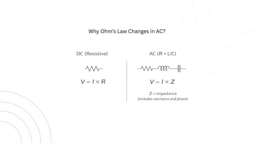
Ohm’s Law Works in DC Because Resistance Is Constant
In basic DC circuits, we often assume the load is a resistor, and its resistance stays constant. Under that condition, current is directly proportional to voltage. If you double the voltage, the current doubles. This is why the Ohm’s Law formula works so well in DC circuit problems.
The important detail is that Ohm’s Law, in its simplest form, assumes the element behaves like a linear resistor. Many DC problems are designed that way on purpose to make analysis easy and predictable.
The Real Reason Ohm’s Law “Fails” in AC Circuits
A more accurate statement is this: Ohm’s Law does not apply to AC circuits in the simple form when inductors and capacitors are present. That is because the circuit’s opposition to current is not only resistance. It also includes frequency-dependent effects that store and release energy.
In an AC circuit:
- Inductors oppose changes in current and create a voltage related to how fast current changes.
- Capacitors oppose changes in voltage and create a current related to how fast voltage changes.
These behaviors introduce reactance, which depends on frequency. As frequency changes, the current changes even if the voltage stays the same. That breaks the “constant R” assumption that makes DC Ohm’s Law feel straightforward.
Resistance vs Reactance: What AC Adds to the Problem?
In AC analysis, we separate opposition into two parts. Resistance (R) dissipates energy as heat. Reactance (X) stores energy and returns it to the circuit, causing a phase shift between voltage and current.
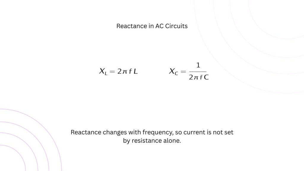
Notice something important: both formulas depend on frequency (f). This is the key reason the simple DC-style approach doesn’t work. A resistor’s value does not change with frequency (in ideal conditions), but an inductor and a capacitor behave very differently at different frequencies.
At higher frequencies, an inductor’s reactance becomes larger (it “blocks” AC more). At higher frequencies, a capacitor’s reactance becomes smaller (it “passes” AC more easily). This is the foundation of filters and many AC applications, but it also explains why is incomplete for AC circuits.
Impedance: The AC Version of “Total Opposition”
Because AC circuits can include resistance and reactance at the same time, engineers use impedance (Z). Impedance is the total opposition to AC, combining resistance and reactance.
The AC form of Ohm’s Law becomes:
V = I x Z
This is the correct idea to use when students ask what replaces Ohm’s Law in AC circuits. The equation still looks similar, but Z is not just a normal number like resistance. It can include phase information as well.
For simple circuits:
- For a pure resistor: Z = R
- For a pure inductor: Z = jXL
- For a pure capacitor: Z = -jXc
The symbol indicates a 90° phase shift relationship in AC analysis. You don’t need to fear it—just remember it represents the fact that voltage and current may not reach their peak at the same time.
Phase Difference: The Concept That Confuses Most Students
One big reason students struggle is that AC introduces a phase. In a pure resistive circuit, voltage and current are in phase, meaning they rise and fall together. In an inductive circuit, current lags voltage. In a capacitive circuit, current leads voltage.
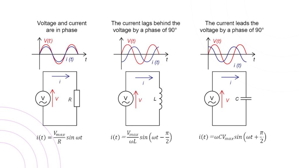
This phase shift matters because power and current behavior depend on it. Two circuits can have the same voltage and the same RMS current, but different real power consumption depending on the phase angle. This is why AC power systems talk about power factor, and why many AC calculations cannot be treated like DC.
When Ohm’s Law Does Apply in AC (Important Clarification)
A helpful clarification is that Ohm’s Law is not “wrong” in AC. It works perfectly in AC circuits that are purely resistive. For example, a heater element or incandescent lamp (approximately resistive) can be analyzed using V = IR for a given operating condition.
The limitation appears when the circuit contains inductors and capacitors, or when frequency effects cannot be ignored. That includes most real AC networks: transformers, motors, RLC circuits, filters, and transmission lines.
A Simple Example: Same Voltage, Different Current
Imagine an AC source of 230 V RMS connected to two different loads. If the first load is a 100 Ω resistor, the current is roughly 2.3 A. But if the load includes an inductor, the impedance increases with frequency, and the current may be much smaller, even if the resistance is still 100 Ω. Using V= I x R would overestimate the current because R is not the full story.
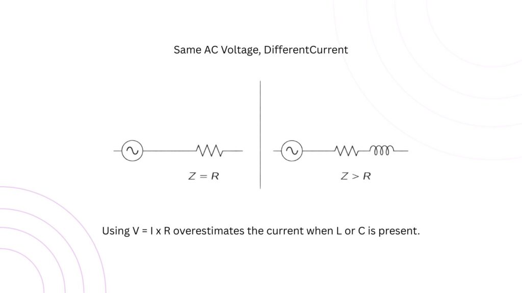
This is a practical example of the limitations of Ohm’s Law in AC circuits: resistance alone cannot predict AC unless the load is purely resistive.
The Correct Way to Think About It
Ohm’s Law does not apply to AC circuits in the simple DC form because AC circuits often include inductors and capacitors, which introduce frequency-dependent reactance and phase shift. The correct approach is to use impedance:
V = I x Z
If you remember just one idea, remember this: AC circuit analysis replaces “R” with “Z,” and adds phase. Once you accept that, most AC topics such as filters, resonance, power factor, and impedance, start to connect naturally.