A buck converter is one of the most important building blocks in power electronics. If you have ever used a phone charger, powered a microcontroller from a battery, or built a DC power supply, there’s a good chance a buck converter was doing the job behind the scenes. The reason is simple: modern electronics often need a stable lower DC voltage, while the available source is usually higher. A buck converter solves that problem efficiently by stepping down the DC voltage with high efficiency. By the end, you’ll understand what a buck converter is, how it works, what the key formulas mean, and what matters most when you start designing one.
What Is a Buck Converter?
A buck converter is a DC-DC step-down converter. It converts a higher input DC voltage into a lower output DC voltage using high-frequency switching and energy storage elements. The key idea is that it does not “burn off” the extra voltage as heat, the way a linear regulator does. Instead, it transfers energy in pulses and smooths the result into a stable output.
The phrase you’ll often see is “high-efficiency DC-DC conversion.” In many practical circuits, buck converters can reach efficiencies above 85–95%, depending on load current, switching frequency, and component choices. When students first meet buck converters, the confusing part is often this: the switch is turning on and off rapidly, yet the output looks like a steady DC voltage. The rest of this article breaks that down in a way that feels intuitive.
Why Buck Converters Are Used So Often?
Buck converters are popular because they reduce voltage efficiently without wasting much power as heat. That matters in battery-powered electronics, where wasted power becomes lost battery life. It also matters in power supplies, where heat management increases cost and complexity.
Another reason buck converters are widely used is flexibility. With the right feedback control, a buck converter can maintain a steady output voltage even if the input voltage changes or the load current varies. That is why you’ll see buck converters in systems like laptops, routers, industrial controllers, and automotive electronics.
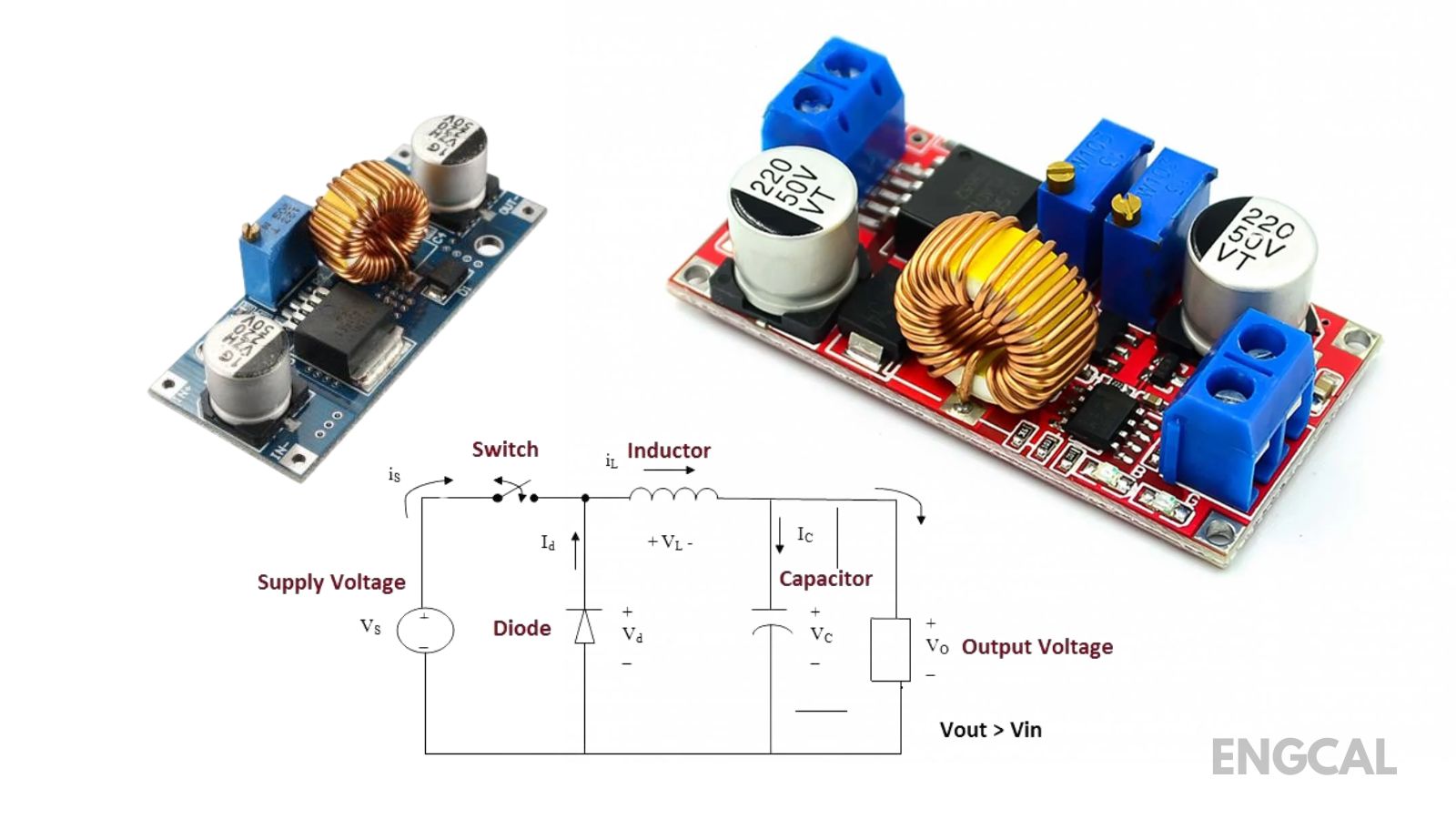
Buck Converter Circuit Overview (Main Parts)
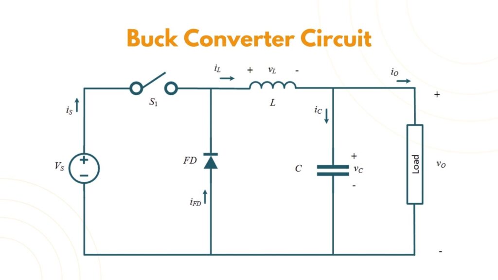
The switch rapidly connects and disconnects the input voltage to the inductor. The inductor resists sudden changes in current, so it naturally smooths current flow and stores energy in its magnetic field. The diode (or synchronous MOSFET) provides a safe path for current when the main switch is OFF. The capacitor smooths the voltage at the output and supplies current during fast switching transitions.
When these parts work together, the output becomes a stable DC voltage even though the switch is pulsing.
Buck Converter Working Principle (How It Actually Steps Down Voltage)
To understand the buck converter working principle, it helps to focus on the inductor because it’s the “heart” of the converter. Inductors store energy when current increases and release energy when current decreases. A buck converter uses this storage-and-release behavior to move energy from input to output in a controlled way.
A switching cycle has two main intervals,
- Switch On State
- Switch Off State
During the switch-On state, the switch connects the input voltage to the inductor. Current through the inductor rises. Energy builds up in the inductor’s magnetic field. The load receives power, and the output capacitor also charges.
During the switch-OFF state, the switch opens. The inductor does not allow current to instantly stop, so it releases stored energy and continues pushing current toward the load. The diode (or synchronous MOSFET) provides a path so the inductor current can keep flowing. The capacitor helps hold the output voltage steady during this transition.
This ON/OFF process repeats at a high switching frequency, often tens or hundreds of kilohertz (or even higher). Because switching happens so fast, the output capacitor and the inductor smooth the pulses into what looks like a steady DC output.
Why Buck Converter Output Voltage Is Lower Than the Input Voltage?
Many learners ask: why buck converter output voltage is lower than the input, even though the input is being connected directly during the ON time?
The most intuitive way to understand it is this: the input is connected only for a fraction of each switching cycle. The inductor and capacitor smooth that pulsed energy. So the output becomes the “average result” of the energy transfer, not the full input voltage.
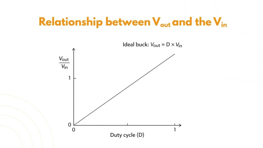
In an ideal buck converter (ignoring losses), the output voltage depends mainly on the duty cycle, which is the ratio of ON time to total switching time. Because the duty cycle is typically less than 1, the output voltage becomes a fraction of the input voltage, which is why it is always lower than the input in normal step-down operation.
Buck Converter Duty Cycle Formula (Key Relationship)
The most important formula in introductory buck converter analysis is the duty-cycle relationship.
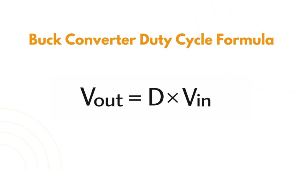
Here, D is the duty cycle (a number between 0 and 1), Vin is the input voltage, and Vout is the output voltage.
This formula is popular because it is simple and explains the step-down behavior clearly. If the duty cycle is 0.5, the converter ideally produces half of the input voltage. If the duty cycle is 0.25, the output ideally becomes one quarter of the input voltage.
In real circuits, the output is slightly lower than the ideal result because of losses in the MOSFET, diode, inductor, resistance, and switching transitions. Still, the duty cycle formula is the foundation for understanding buck converter behavior.
Continuous Conduction Mode vs Discontinuous Conduction Mode (CCM vs DCM)
A topic that often surprises beginners is that buck converters can behave differently depending on load current. This is where the CCM vs DCM buck converter matters.
In continuous conduction mode (CCM), the inductor current never falls to zero during a switching cycle. This typically happens at medium to heavy loads. CCM is often easier to analyze using the simple duty cycle relationship, and it usually produces smoother current flow.
In discontinuous conduction mode (DCM), the inductor current drops to zero for part of the cycle, which usually occurs at light loads. In DCM, the simple “Vout = D × Vin” relationship does not hold perfectly because the inductor fully discharges before the next cycle begins. The converter’s behavior becomes more dependent on load, inductance, and switching frequency.
If your goal is practical design, the key takeaway is that a buck converter should be designed to operate in the mode that suits your application. Many power supplies aim for CCM during normal load because it reduces ripple and improves stability.
Buck Converter Ripple: Why the Output Isn’t Perfectly Flat?
Even though a buck converter produces DC output, it is not perfectly ripple-free. Output voltage ripple comes from the charging and discharging of the capacitor and the ripple current flowing through the inductor.
Ripple matters because sensitive electronics, like analog circuits, RF modules, or precision sensors, can malfunction or become noisy if the ripple is too high. Designers control ripple by selecting the right inductor value, choosing a low-ESR capacitor, and setting an appropriate switching frequency.
A practical way to keep readers engaged is to remember this: when a buck converter “looks unstable,” the issue is often ripple and filtering, not the duty cycle formula itself.
Buck Converter Efficiency Calculation (What Controls Efficiency)
Efficiency is a major reason buck converters are used. If you are searching for buck converter efficiency calculation, the core definition is:
Efficiency (%) = (Pout / Pin) × 100
Where output power is Vout × Iout and input power is Vin × Iin.
But what controls efficiency in real hardware? Losses come from several sources. Conduction losses happen because real components have resistance. The MOSFET has an on-resistance, the inductor has winding resistance, and a diode has a forward voltage drop. Switching losses happen because the MOSFET does not turn on and off instantly, so there is a brief time where voltage and current overlap, creating heat. There are also losses associated with gate driving, diode recovery, and core losses in the inductor.
A high-level design goal is simple: reduce resistive losses at high current and reduce switching losses at high frequency. This is why choosing the switching frequency is always a trade-off: a higher frequency makes the inductor and capacitor smaller, but it can reduce efficiency if switching losses dominate.
Buck Converter Inductor Selection (Beginner-Friendly Design Insight)
For many beginners, buck converter inductor selection is where the design starts to feel “real.” The inductor affects ripple current, output ripple, and whether the converter stays in CCM at your expected load.
A larger inductance generally reduces ripple current, which can make the output voltage smoother and reduce stress on components. However, a very large inductor can increase size, cost, and response time. A very small inductor can lead to high ripple current, noise, and overheating.
Two practical ratings matter more than people expect. The first is the saturation current. If the inductor saturates, its inductance effectively collapses, ripple current rises sharply, and the converter can become unstable or fail. The second is DC resistance (DCR). Higher DCR increases conduction loss, which reduces efficiency and creates heat.
A good beginner mindset is: pick an inductor that does not saturate at peak current, has reasonably low DCR, and gives acceptable ripple for your load.
Output Capacitor Selection (Often Overlooked)
The output capacitor does more than “filter ripple.” It supplies current during switching events and helps maintain output stability. In real designs, capacitor ESR (equivalent series resistance) can strongly influence ripple voltage and transient response. Low-ESR capacitors typically produce lower ripple, but stability depends on the converter’s control method, so capacitor choice should match the IC’s recommendations.
In practical engineering, many buck converter problems that look “mysterious” are solved by improving capacitor selection and layout.
Common Mistakes in Buck Converter Design
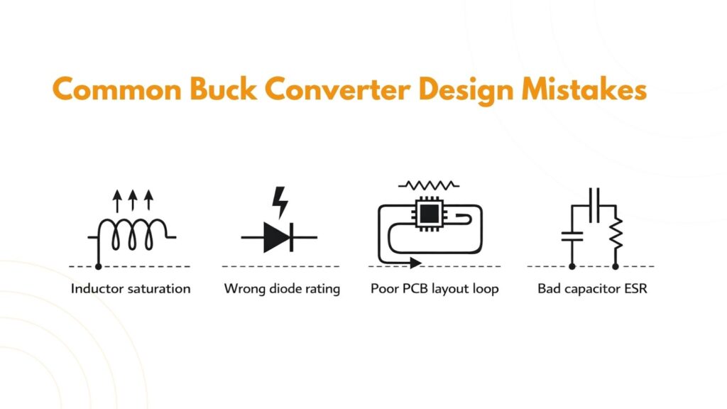
Even with correct formulas, real circuits can fail due to small design mistakes. A few mistakes appear again and again. People often ignore peak current and choose an inductor that saturates. Others select a diode with poor reverse recovery or too low a current rating. Some designs choose a MOSFET with low on-resistance but high gate charge, which can actually reduce efficiency at higher switching frequencies. Layout is another big one: long loops and poor grounding can create noise, ringing, and unstable behavior even when the schematic is correct.
If you are designing your first buck converter, a good rule is to treat component ratings and PCB layout as part of the design, not as an afterthought.
Buck Converter Applications (Where You’ll See It)
Buck converters are used in almost every electronics area where voltage needs to be reduced efficiently. They are common in embedded boards that step 12 V down to 5 V or 3.3 V, in battery devices that regulate varying battery voltage, and in high-current systems like CPUs and GPUs where power efficiency is critical.
Once you recognize buck converters, you start seeing them everywhere.
Buck Converter vs Linear Regulator (Quick Practical Comparison)
A linear regulator is simple and clean, but it wastes power as heat when stepping down the voltage. A buck converter is more complex and produces ripple, but it saves a lot of energy. If your input voltage is only slightly higher than your output voltage and the current is small, a linear regulator can be fine. But when the voltage difference or current becomes significant, a buck converter is typically the better choice.
Final Summary
A buck converter is a high-efficiency DC-DC step-down converter that produces a lower output voltage from a higher input voltage using switching, an inductor, and a capacitor. The buck converter duty cycle formula explains the ideal voltage relationship, while real-world design requires attention to conduction losses, switching losses, inductor selection, and output capacitor behavior. Understanding CCM vs DCM buck converter operation helps you predict performance at different loads, and learning buck converter efficiency calculation helps you evaluate real designs.