RC Time Constant Calculator with Example is one of the fastest ways to stop guessing in electronics. You see a capacitor voltage creeping up on an oscilloscope and you wonder, “Is this normal, or is something wrong?” In real circuits, that slow rise or fall is often the difference between a clean reset pulse and a microcontroller that behaves randomly, or the difference between a stable sensor filter and a signal that lags too much. Once you understand the RC time constant, you can predict that waveform before you even power the board.
I have used RC networks in everything from simple debouncing circuits to timing delays, analog filters, and soft-start behavior in power supplies. The math is not hard, but it is easy to apply incorrectly if you skip the physical meaning. In this article, I will explain what the RC time constant really means, then walk you through charging and discharging calculations step by step, including a worked example you can reuse for your own designs.
What is an RC time constant?
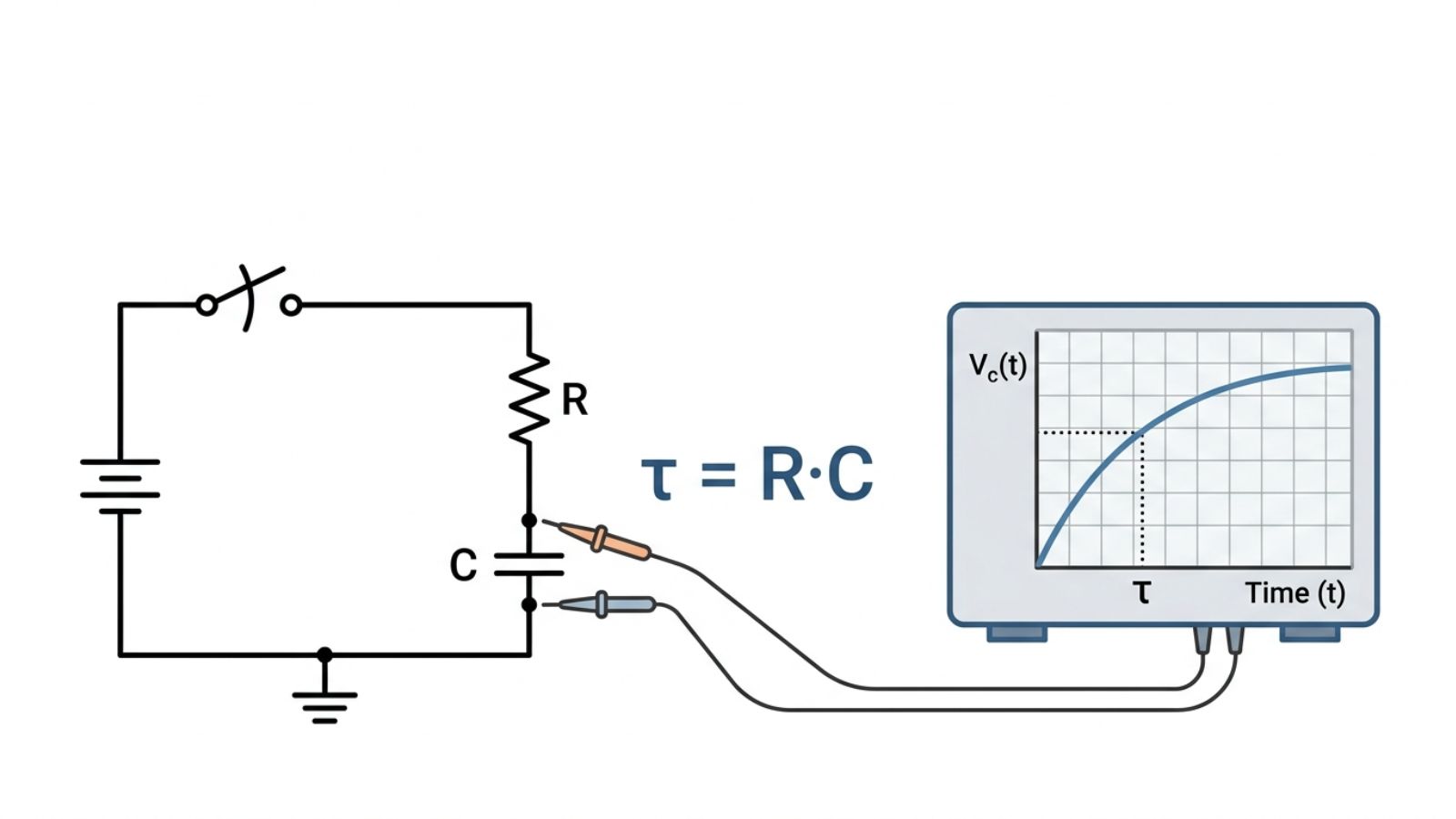
An RC circuit consists of a resistor and a capacitor connected so that the capacitor voltage changes over time. The “time constant” is written as τ (tau). It is defined as: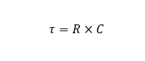
R is resistance in ohms (Ω). C is capacitance in farads (F). τ is in seconds (s).
The time constant is not “the time it takes to charge fully.” That is the first misunderstanding I correct when teaching this. τ tells you the characteristic speed of the exponential change. It is the point where the capacitor has moved a specific fraction toward its final value.
For a charging capacitor, after one time constant, the capacitor voltage reaches about 63.2% of the way from its starting voltage to its final voltage. For a discharging capacitor, after one time constant, the capacitor voltage drops to about 36.8% of its starting value.
Those numbers come from e to the minus power. You do not need to memorize the math behind it to use it correctly, but you do need to remember the meaning. One τ is a strong milestone, not the endpoint.
Why does RC charging and discharging look “curved” on a scope
The resistor limits current. The capacitor voltage changes because current charges or discharges it. As the capacitor voltage changes, the voltage across the resistor changes, so the current changes too. That is why the slope is steep at the beginning and slows down later.
At the instant you start charging from a lower voltage, the capacitor looks like a short for that moment. Current is high. The voltage rises quickly. As the capacitor voltage approaches the supply, the current falls, and the rise slows.
During discharge, it is the same story in reverse. At the beginning, there is more voltage across the resistor, so the current is larger. As the capacitor voltage drops, current falls, and discharge slows.
This “fast then slow” behavior is exactly what the exponential equations capture.
The two equations you use most in practice
There are two core equations. One is for charging toward a final voltage. The other is for discharging toward zero or toward a lower final voltage.
Capacitor charging equation
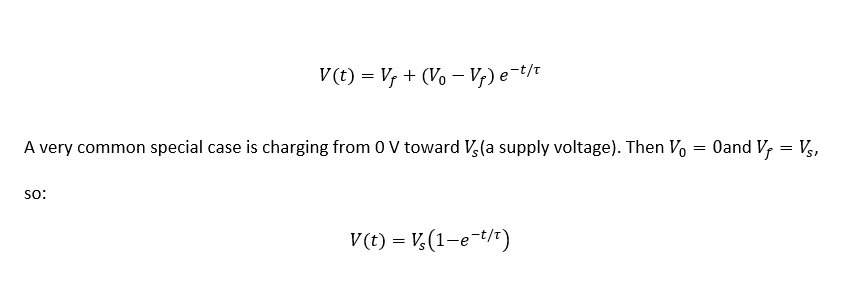
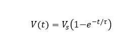
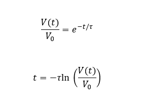
If a capacitor starts at an initial voltage and charges toward a final voltage, the capacitor voltage at time t is:
Capacitor discharging equation
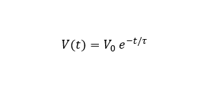
If a capacitor starts at V0 and discharges toward 0 V through a resistor, the voltage at time t is:
If it discharges toward a non-zero final voltage, use the more general form that looks like the charging equation.
These equations are the engine behind any RC time constant calculator. The calculator just saves you time and reduces arithmetic errors.
Step-by-step method for RC charging calculations
When you use an RC time constant calculator, you should still understand the steps behind it. That helps you verify results and spot wrong assumptions.
Start by identifying the resistance that the capacitor actually sees. This is not always the resistor value printed in the schematic box. If there are other resistances in parallel or series, you need the equivalent resistance from the capacitor’s perspective.
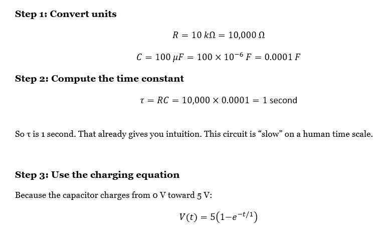
Then calculate the time constant: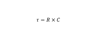
Then choose the correct voltage equation. If you are charging toward a supply voltage, use:
If you are charging toward another level, use the general form.
Finally, plug in t and solve for V, or plug in V and solve for t. Solving for time is common because engineers often ask, “How long until the capacitor reaches 3.3 V?” or “How long until it drops below 0.8 V?”
When solving for time during charging from 0 V to Vs, rearrange:
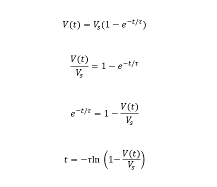
That last line is extremely useful.
Step-by-step method for RC discharging calculations
Discharging is simpler when it goes to zero. You use:
If you want to find time to reach a particular voltage V(t), rearrange:
This equation answers questions like, “How long does my reset capacitor hold the pin low?” or “How long until the voltage is less than 10% of the initial value?”
Worked example: RC charging step by step
Let’s use values that appear constantly in real circuits.
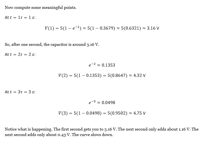
Assume you have a resistor (r = 10 kΩ) and a capacitor (C =100 uF). The capacitor starts at 0 V and charges from a 5 V supply through the resistor. We want to compute the capacitor voltage at different times, and also the time required to reach specific voltage thresholds.
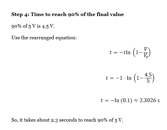
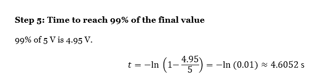
So it takes about 4.6 seconds to reach 99% of the final. That is a key design insight. “Almost fully charged” can take several time constants.
In practice, many engineers use rules of thumb. Around 3τ is about 95%. Around 5τ is above 99%. These are handy for quick design estimates.
Worked example: RC discharging step by step
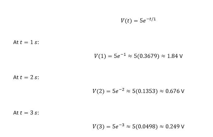
Now, assume the same R and C. The capacitor starts at 5 V and discharges through the resistor to 0 V.
We already know τ is 1 second.
The discharge equation is:
Now solve for the time to drop below a threshold. This is common in reset circuits.
Suppose you want to know when the capacitor falls below 1.0 V.
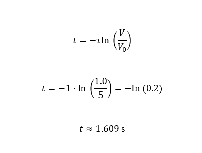
So it takes about 1.61 seconds to drop from 5 V to 1 V with τ = 1 second.
What an RC time constant calculator should output
A good RC time constant calculator should not only give τ. It should also help you answer the two real questions engineers ask.
One question is, “What is the capacitor voltage at time t?” The calculator should let you enter R, C, initial voltage, final voltage, and time, then output V(t).
The other question is, “How long until the capacitor reaches a voltage threshold?” The calculator should let you enter R, C, initial and final voltage, and target voltage, then output t. You can calculate the RC time constant easily using engcal to avoid mistakes.
Practical engineering notes that improve accuracy
The RC time constant you calculate on paper assumes ideal parts. In the field, a few effects shift behavior. These effects matter most when your time constant is long or your thresholds are tight.
Capacitor tolerance is often wider than people expect. A typical electrolytic might be ±20%, sometimes worse. That means τ can vary by ±20% just from capacitance. If timing is critical, consider a capacitor with a tighter tolerance, or choose a design that still works over a wide τ range.
Capacitor leakage current matters when resistor values are large. If you use a very high resistor, the leakage can become comparable to the intended current. Then the capacitor may never reach the expected final voltage, or it may discharge faster than predicted.
The input impedance of whatever you connect to the capacitor matters too. A microcontroller pin, an ADC input, or a scope probe adds a parallel resistance. That effectively reduces the resistance seen by the capacitor. It reduces τ. For example, a 1 MΩ scope probe can significantly load a circuit that uses 1 MΩ timing resistors.
Series resistance in the capacitor, often called ESR, does not change the exponential shape much for slow RC timing, but it can affect fast edges and initial current spikes. In timing circuits, it is usually not the first-order issue. In filters and pulse shaping, it can be.
Also, remember that “the resistor in the diagram” is not always the only resistance. If you are charging through a transistor, a diode, or a pull-up network, the equivalent resistance can be different in charge versus discharge. That creates different time constants for rising and falling edges, which can be useful if it is intentional.
Common mistakes, explained in plain language
A common mistake is mixing units. kΩ and Ω errors and µF versus nF errors are extremely common. If your timing is off by a factor of 1000, it is almost always a unit issue.
Another mistake is assuming the capacitor fully charges in one τ. It does not. One τ gets you to about 63% of the way. If you need the capacitor to cross a threshold near the supply voltage, you must design for multiple τ.
Another mistake is forgetting that the initial voltage matters. The general equation uses both the starting voltage and the final voltage. If the capacitor starts partially charged, the time to reach a threshold changes.
A final mistake is ignoring loading. The RC time constant is based on the resistance seen by the capacitor. If your circuit loads the node, your effective R changes. Your timing changes with it.
Where this shows up in real circuits
RC timing is used in reset circuits, power-on delay networks, and soft-start pins. It is used in debouncing. It is used in analog filtering for sensors. It is used in PWM smoothing when you want an average voltage. It is used in coupling and bias networks in amplifiers.
The reason it shows up everywhere is that it is cheap, stable enough for many applications, and easy to predict once you calculate τ correctly.
FAQ
People often ask whether higher resistance always means slower charging. In the basic RC model, yes. Increasing R increases τ, so the capacitor voltage changes more slowly. But if leakage currents become important, extremely large R values can behave in unexpected ways. The capacitor may not reach the expected final voltage.
People also ask how to choose R and C for a desired delay. The simplest approach is to choose a capacitor value that is practical and stable, then compute R from. After that, verify threshold timing using the full equation, not just τ. A 1-second time constant does not mean a 1-second delay to any arbitrary threshold.
Another frequent question is why measured timing does not match the calculation. In most cases, it is tolerance, leakage, or loading. If you check those three, you usually find the cause quickly.
References and verification
The RC time constant relationships used here are standard first-order circuit results. You will find them in basic circuit analysis texts and electronics references. The worked example values were checked by computing τ, then using the exponential equations to compute voltage at 1τ, 2τ, and 3τ, and by solving the threshold times using the natural log rearrangement.