If you have ever stood next to a large induction motor when it starts up, you know the experience. There is a brief shudder, a loud hum, a spike in the current reading on the panel, and then the motor settles into smooth operation. Most people write that off as just how motors work. But as an engineer with over a decade of hands-on experience in power systems and motor drives, I find that moment incredibly interesting. What you are witnessing is a rapid, dramatic shift in slip, current, and torque, all happening within a few seconds.
This article is going to walk you through what induction motor slip at startup actually looks like, how it differs from slip under steady-state load, and why all of this matters in real engineering practice. Whether you are a first-year undergraduate trying to make sense of your machine’s textbook, or a working engineer brushing up before a commissioning job.
What Is Slip?
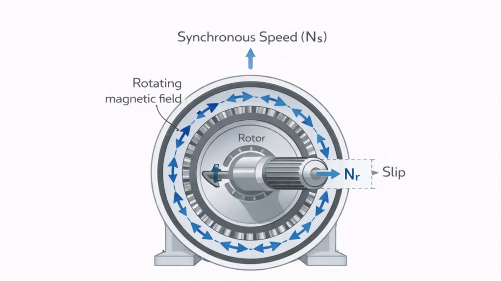
Before we get into startup behavior, let us make sure the foundation is solid. An induction motor works because its stator creates a rotating magnetic field. That field spins at a speed called the synchronous speed, which depends only on the supply frequency and the number of poles in the motor.
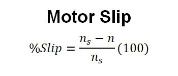
Here is the key point: the rotor cannot spin at the same speed as that magnetic field. If it did, there would be no relative motion between the field and the rotor conductors, no induced current, no force, and no torque. The rotor always spins a little slower than the field. That speed difference is called slip.
Slip is expressed as a decimal or a percentage. When the rotor is standing still, slip is 1.0 or 100 percent. When the rotor is spinning at synchronous speed (which never actually happens under load), slip would be zero.
Important concept: Slip is not a flaw or inefficiency in an induction motor. It is the fundamental mechanism that allows the motor to produce torque at all. A motor with zero slip would produce zero torque. The goal is not to eliminate slips, but to understand and control them.
What Happens to Slip the Moment You Start the Motor
The startup phase of an induction motor is where the most dramatic behavior occurs. At the instant the motor is switched on, the rotor is completely stationary. Slip is at its maximum value of 100 percent. From that moment, as the motor accelerates, slip decreases steadily until the motor reaches its operating point.
But what does 100 percent slip actually mean in practice? Let me walk through the key effects
High Rotor Frequency at Startup
When slip is 100 percent, the frequency of the currents induced in the rotor is equal to the stator supply frequency. So on a 50 Hz system, the rotor sees 50 Hz currents at startup. As the motor accelerates and the slip drops, the rotor frequency drops with it. By the time the motor reaches full operating speed with a slip of around 3 percent, the rotor frequency is only about 1.5 Hz.
This has a significant effect on rotor impedance. At 50 Hz, the inductive reactance of the rotor windings is high, which changes how current flows through the rotor bars. This is actually useful in some motor designs. Deep-bar and double-cage rotors take advantage of this effect to improve starting performance, a concept we will touch on shortly.
The Startup Current Surge
Here is the number that surprises most undergrads when they see it for the first time. At startup, an induction motor typically draws between 6 and 8 times its rated full-load current. In some designs, it can go as high as 10 times. This is called the inrush current or starting current. The reason is straightforward. At a standstill, the rotor is not generating any back-EMF because it is not moving. From the stator’s perspective, the motor looks almost like a short circuit. The only thing limiting current is the stator and rotor impedances, which are relatively low.
Example:
On a 75 kW induction motor I helped commission for a water treatment plant, the startup current peaked at 6.8 times full-load current. That surge lasted about 5 seconds before the motor reached operating speed, and the current dropped to normal. The protection relay settings had to be carefully chosen to ride through that transient without tripping, while still protecting against real fault conditions.
Starting Torque Characteristics
You might expect that with such high current at startup, the motor would also produce very high torque. In reality, the starting torque of a standard squirrel-cage motor is usually only between 1.5 and 2.5 times rated torque. It is nowhere near proportional to the starting current.
The reason is the power factor. At high slip, the rotor circuit has significant inductive reactance, which causes the rotor current to lag behind the voltage. The torque produced depends not just on the magnitude of the rotor current, but on its phase relationship with the air-gap flux. The lagging power factor at startup reduces the effective torque production significantly compared to what the current magnitude alone would suggest.
How Slip Behaves Under Steady-State Load
Once the motor has accelerated and is running normally, the relationship between slip and load is much simpler and more predictable. At this point, the motor is operating in what engineers call the stable region of the torque-speed curve.
The Stable Operating Region
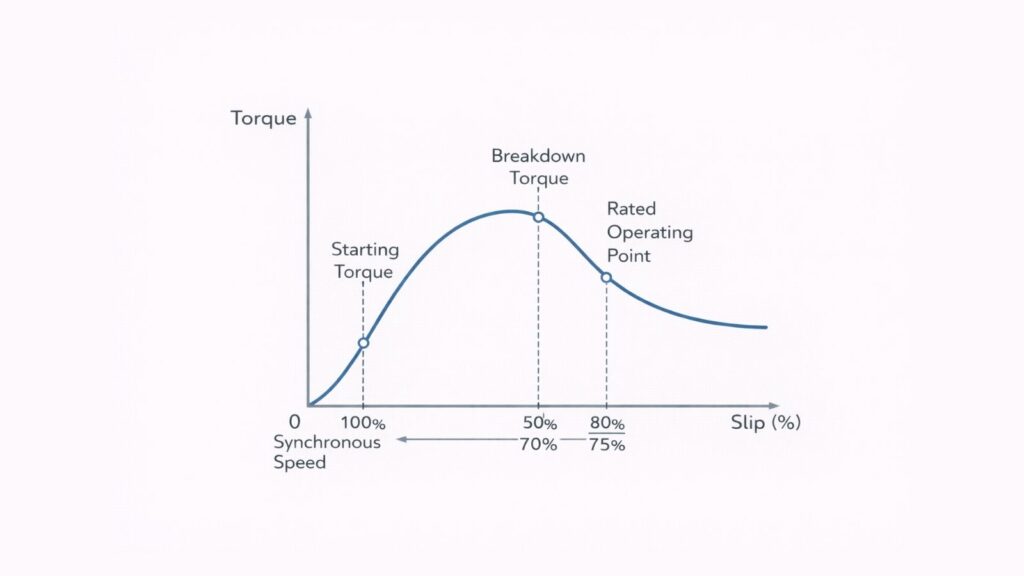
The torque-speed curve of an induction motor has a shape that every electrical engineering student needs to understand. Starting from zero speed and moving toward synchronous speed, torque rises, reaches a peak called the breakdown torque or pull-out torque, and then drops back toward zero at synchronous speed.
Normal operation happens on the right-hand side of that peak, in the region between breakdown torque and synchronous speed. In this region, the motor has a natural self-regulating behavior. If the load increases, the rotor slows slightly, slip increases, rotor current increases, and torque increases to match the new load. The system finds a new equilibrium automatically. This is why induction motors are considered stable and reliable workhorses in industry.
Slip Is Roughly Proportional to Load in Normal Operation
In the stable region, there is an approximately linear relationship between torque (which reflects load) and slip. If you double the load on the motor shaft, the slip roughly doubles as well, within the normal operating range.
Here is a concrete example. Consider a 4-pole motor running on a 50 Hz supply. Its synchronous speed is 1500 RPM. At no load, it might spin at 1498 RPM, which is a slip of only about 0.13 percent. At full rated load, it might spin at 1455 RPM, a slip of 3 percent. At moderate load, say 50 percent of rated, you would expect it to run around 1478 RPM with a slip of about 1.5 percent. These differences are measurable and meaningful, especially in applications where speed accuracy matters, such as conveyor systems, paper mills, or precision fans.
The Core Difference: Startup Slip vs. Load-Driven Slip
This is the part of the topic that confuses students most often, and I want to be as clear as possible here. Startup slip and load-driven slip involve the same formula, but they are driven by completely different physical mechanisms.
At Startup: Inertia Is the Driver
When the motor first starts, slip is at 100 percent, not because the load is heavy, but because the rotor has not moved yet. The rotor has mechanical inertia. It takes time and energy to accelerate it to operating speed. During this acceleration phase, the motor is working against the combined inertia of the rotor, the shaft, the coupling, and whatever mechanical load is attached.
Think of it like pushing a heavy trolley from a standstill. The force you need in that first second is much greater than the force needed to keep it rolling at a constant speed. The startup phase of an induction motor is exactly that initial push, played out electromagnetically. During startup, rotor frequency is high, rotor reactance is significant, and the equivalent circuit of the motor is relatively complex. Textbook simplified equivalent circuits that work fine for steady-state analysis are not accurate for startup transient calculations.
Under Load: Torque Balance Is the Driver
Once the motor is running, slip is determined by the balance between the electromagnetic torque produced by the motor and the mechanical torque demanded by the load. The motor continuously adjusts its operating point to maintain this balance.
At normal operating slip (between 2 and 5 percent for most standard motors), rotor frequency is very low. On a 50 Hz system, the rotor might be seeing only 1 to 2.5 Hz. At such a low frequency, rotor inductive reactance is almost negligible. The rotor circuit is essentially resistive, which is why steady-state analysis using simplified equivalent circuits works well.
Real-World Consequences of High Startup Slip
Understanding startup slip is not just an academic exercise. It has direct consequences that you will deal with regularly as a practicing engineer.
Thermal Stress on the Motor
The high current during startup generates heat in both the stator windings and the rotor bars. In a direct-on-line start, this heat is dumped into the motor in a matter of seconds. Most motors are rated for a limited number of starts per hour precisely because of this thermal loading.
I once responded to a site call where a conveyor motor was repeatedly failing its rotor bars. After investigating, we found the operators were restarting the motor every few minutes after minor faults, far exceeding the manufacturer’s recommended starts-per-hour limit. The rotor bars were simply cracking from cumulative thermal fatigue. The fix was a proper VFD installation and an operator training session on startup limits.
Voltage Dip on the Supply Network
The large inrush current at startup creates a temporary voltage dip on the supply busbar. For small motors on a stiff grid, this is usually not a problem. But for large motors, or motors on a weak supply, the voltage dip can be severe enough to trip other equipment, cause lighting to flicker noticeably, or even prevent the motor itself from producing enough torque to start.
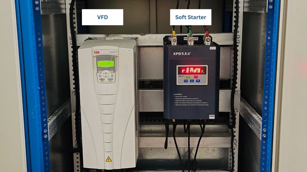
This is one of the main reasons soft starters and VFDs exist. By limiting the inrush current, they reduce the voltage dip and make the startup gentler on both the motor and the network.
Protection Relay Coordination
Setting overcurrent protection for a motor feeder requires careful thought about the startup current profile. The relay must be set high enough to ride through the startup inrush without tripping, but low enough to detect genuine overloads and faults. Getting this balance wrong leads to either nuisance trips during normal startups or protection that is too slow to prevent damage in a real fault.
Modern motor protection relays include specific startup supervision functions, including thermal memory and acceleration time monitoring, precisely because the startup phase is so different from normal operation.
Motor Design Features That Address Startup Slip
Motor manufacturers have developed several design strategies to improve startup performance without sacrificing running efficiency. These are worth knowing because they directly relate to how startup slip is managed in practice.
Deep-Bar and Double-Cage Rotors
Standard squirrel-cage rotors have relatively uniform rotor bars. In a deep-bar rotor design, the rotor bars are made tall and narrow. At high frequency (high slip, startup), the skin effect pushes current to the top of the bar, reducing the effective cross-section and increasing effective rotor resistance. Higher rotor resistance at startup means better starting torque.
At low frequency (low slip, running), current distributes uniformly across the full bar cross-section, giving low resistance and good running efficiency. The motor effectively has two different rotor resistance values depending on operating frequency, using nothing but the laws of physics.
The double-cage design takes this further by literally having two concentric sets of rotor bars, one outer cage with high resistance and one inner cage with low resistance. The outer cage dominates at startup; the inner cage dominates in running. This is a clever engineering solution that has been in use for decades.
NEMA Design Classes
In North America, NEMA classifies standard induction motors into design classes based on their torque-speed characteristics:
- Design B is the most common general-purpose motor. It has moderate starting torque, limited starting current, and low running slip. Good for pumps, fans, and compressors that start unloaded.
- Design C has a higher starting torque with controlled starting current. Used for applications that must start under load, such as loaded conveyors or reciprocating compressors.
- Design D has a very high starting torque and a relatively high running slip. Used for high-inertia loads like punch presses, cranes, and elevators.
- Design A is similar to Design B but allows a higher starting current. Used in applications where the supply system can tolerate the inrush.
Selecting the right design class depends entirely on understanding the startup torque and current requirements of your specific application.
Starting Methods and Their Effect on Slip Behavior
The starting method you choose for a motor fundamentally changes how slip evolves during startup. This is a critical decision in any motor drive application.
Direct-On-Line Starting
Direct-on-line (DOL) starting connects the motor directly to the full supply voltage at startup. Slip starts at 100 percent, the full inrush current flows immediately, and the motor accelerates as fast as its torque-speed characteristic, and the load inertia allows. This is the simplest and cheapest starting method, but it places the most stress on the motor and the supply network.
DOL starting is acceptable for small motors (typically below 11 kW in many countries) or for applications where the supply is stiff enough to handle the inrush without causing problems.
Soft Starters
A soft starter reduces the voltage applied to the motor during startup, which reduces the inrush current. Because torque is proportional to the square of voltage, reducing voltage to 70 percent cuts starting torque to about 49 percent of what it would be at full voltage. This makes soft starters suitable only for applications with light starting loads, such as centrifugal pumps and fans.
The slip behavior with a soft starter is similar to DOL starting in that the motor still starts from 100 percent slip. The difference is that the reduced voltage slows the acceleration and reduces the current peaks.
Variable Frequency Drives
A VFD is the most sophisticated starting method. It ramps up both voltage and frequency together, maintaining the motor flux at its rated level throughout startup. The motor effectively operates near its rated slip point during the entire acceleration ramp, rather than starting at 100 percent slip and working down.
This approach is significantly gentler on the motor and virtually eliminates the startup current surge. VFDs also provide continuous speed control during running, which makes them the preferred choice in energy-sensitive applications like pump and fan systems.
Real-World Example:
On a 110 kW cooling tower fan motor, we replaced a DOL starter with a VFD. The startup current went from 7 times full-load current (lasting about 8 seconds) to approximately 1.1 times full-load current throughout a 15-second ramp. The motor ran cooler, the supply voltage dip disappeared, and the fan blades experienced significantly less mechanical stress at startup. Energy savings during running were an added benefit.
Key Takeaways for Students and Practicing Engineers
After more than ten years in the field, here are the points I find myself returning to again and again when dealing with induction motor slip at startup.
- Startup slip and running slip are governed by different mechanisms. At startup, inertia is the cause of high slip. Under load, the torque balance sets the operating slip. Do not confuse the two.
- High startup current is normal. Seeing 6 to 8 times full-load current during startup is expected for a direct-on-line motor start. It is not a fault condition. Your protection relay settings must account for this.
- Slip is a useful diagnostic tool. A motor running with significantly more slip than its nameplate rating suggests could indicate rotor bar damage, supply voltage imbalance, or overloading. Measuring shaft speed with a tachometer and comparing it to synchronous speed is a quick and cheap field check.
- Your starting method choice must match your load profile. Light-starting loads like centrifugal pumps can use soft starters. Heavy-starting loads like loaded conveyors or compressors need full torque at startup, which means DOL or VFD starting.
- Thermal limits matter at startup. Every motor has a maximum number of starts per hour. Exceeding this limit causes cumulative rotor and winding damage that may not show up immediately but leads to early failure.
- The torque-speed curve is your best friend. Understanding where your motor operates on that curve, both at startup and at the running condition, gives you a complete picture of its behavior under any load scenario.
Conclusion
Induction motor slip at startup is one of those topics that sits right at the intersection of theory and practice. The formula is simple, but what happens physically during those first few seconds of motor operation is rich with engineering detail.
At startup, the motor is fighting inertia with 100 percent slip, high rotor frequency, complex impedance effects, and a current surge that can stress the supply network and the motor itself. Once it reaches running speed, the picture changes completely. Slip settles to a small, steady value determined entirely by the load on the shaft, and the motor enters a self-regulating equilibrium where torque and speed stay balanced.
Understanding the difference between these two regimes is not just useful for passing exams. It informs how you select motors, set protection relays, choose starting methods, diagnose field problems, and design motor-driven systems that are reliable and efficient over the long term.
Take the time to really internalize the torque-speed curve and the slip equation. They are simple tools that unlock a deep understanding of one of the most widely used machines in the history of engineering.