
Power factor is one of those topics that feels confusing at first. Many students memorize formulas. Many technicians use rules of thumb. But the idea becomes simple when you connect it to something real: current and losses. Power factor changes how much current a load draws for the same useful work. It affects cable heating. It affects the voltage drop. It affects transformer loading. It also affects electricity bills in many commercial and industrial settings. This guide is written to make power factor explained in a clean and practical way. We will compare kW vs kVA vs kVAR.
What Is Power Factor?
Power factor (PF) tells you how effectively electrical power is being converted into useful work. In AC systems, voltage and current can be out of phase. When that happens, not all the power flowing from the source becomes useful work.
Some of it “oscillates” back and forth between the source and the load. This oscillating part is called reactive power. It is needed to create magnetic fields in motors and transformers. But it does not do real mechanical work by itself.
So power factor is a measure of how much of the supplied power is real power.
In simple terms:
- A high power factor means the system uses power efficiently.
- Low power factor means more current is needed for the same useful output.
If you only want one sentence for power factor explained, use this:
Power factor shows how much of the supplied electrical power becomes useful power.
The Three Power Terms: kW, kVA, and kVAR
To understand power factor, you must separate power into three types. This is the core reason people get confused.
Real power (kW)
Real power is the power that does useful work. It turns into heat, light, motion, and output energy. It is measured in kilowatts (kW).
Real power is what actually runs your machine. It is what you “want.”
Apparent power (kVA)
Apparent power is the product of RMS voltage and RMS current. It represents what the supply must deliver. It is measured in kilovolt-amperes (kVA).
Apparent power is what your transformer and cables must handle. It is about capacity.
Reactive power (kVAR)
Reactive power is the power that moves back and forth due to inductors and capacitors. It supports magnetic and electric fields. It is measured in kilovolt-ampere reactive (kVAR).
Reactive power is needed for many AC loads. But it increases current and losses.
When you hear kW vs kVA vs kVAR, think:
- kW is useful work
- kVA is the total supply burden
- kVAR is the non-working “field” part
That is the clean way to remember it.
Power Factor Formula (Simple Meaning)
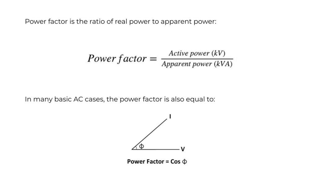
Here is the phase angle between voltage and current.
You do not need to fear the angle. Just remember what it represents: misalignment between voltage and current. When voltage and current are aligned, the angle is small, and PF is high. When they are far apart, PF drops.
Why Power Factor Matters (The Practical Reason)
Power factor matters because current matters. And current creates losses.
For a given real power (kW), a lower power factor means a higher current. Higher current causes:
- Higher heating in cables
- Higher voltage drop
- Higher losses in transformers
- Reduced usable capacity in generators and UPS systems
- Possible penalties in industrial billing
This is the most important real-world idea in power factor explained content.
Many people ask: “If kW is the useful power, why should I care about kVA?” The answer is simple: your system components are rated by current and kVA, not just by kW. If PF is low, you need larger equipment for the same kW.
A Simple Example (Same kW, Different kVA)
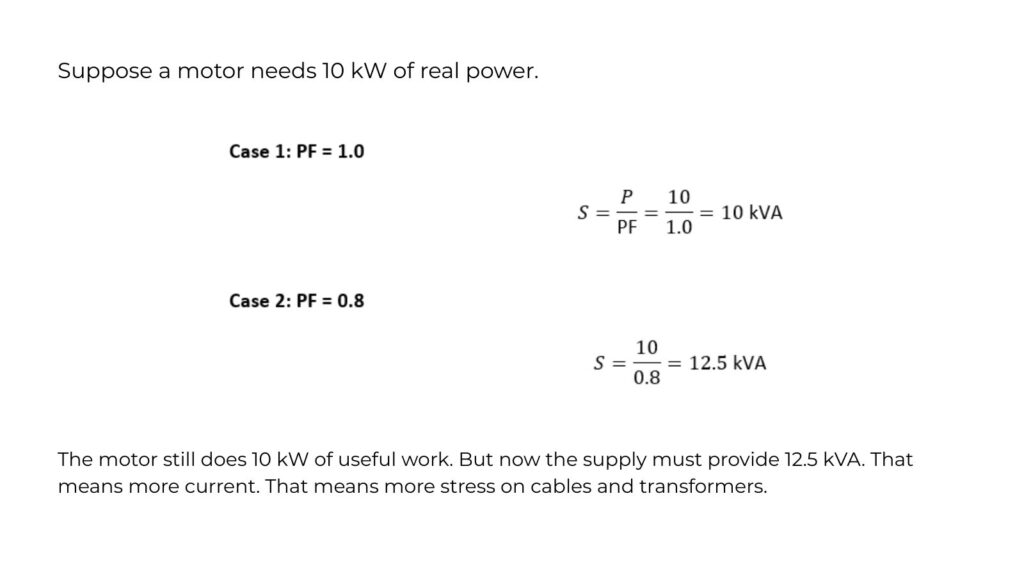
The motor still does 10 kW of useful work. But now the supply must provide 12.5 kVA. That means more current. That means more stress on cables and transformers.
This is a perfect “feel it” example for power factor explained.
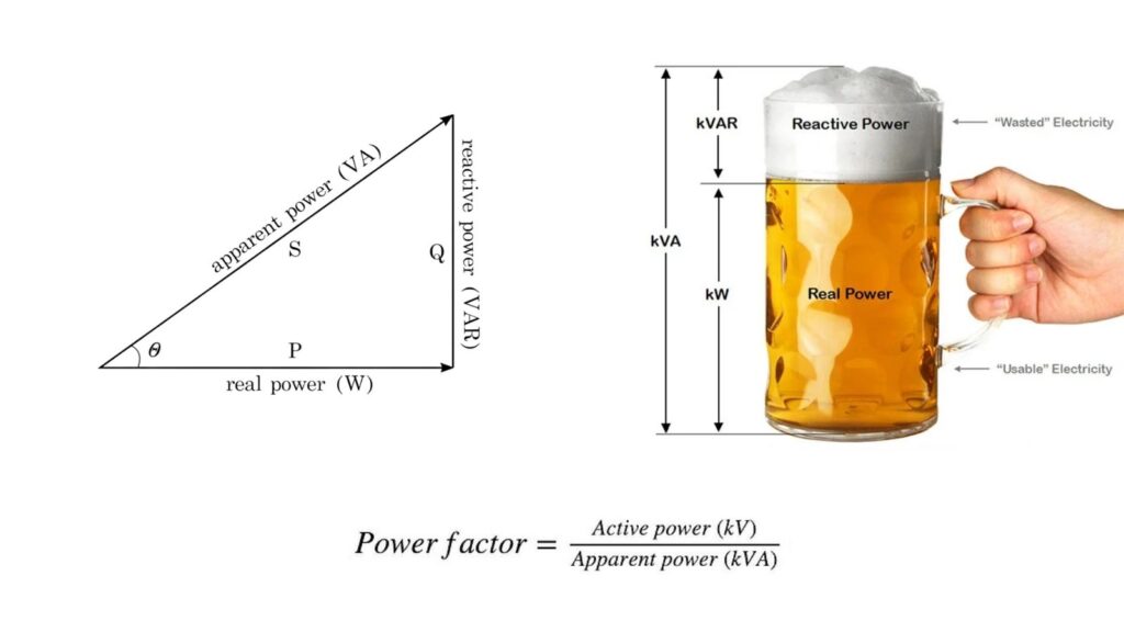
The Power Triangle (The Picture Behind kW, kVA, kVAR)
Engineers often visualize these three powers as a triangle.
- Horizontal side is the real power in kW
- Vertical side is reactive power in kVAR
- Hypotenuse is the apparent power in kVA
From this triangle, you can also see why PF drops when reactive power increases. The hypotenuse grows, while the useful horizontal part stays the same. You do not need to draw the triangle every time. But it helps you understand what is happening.
What Causes Low Power Factor?
Inductive loads mainly cause low power factor. Inductors store energy in magnetic fields. That includes many common devices:
- induction motors
- transformers
- relays and solenoids
- fluorescent lighting with magnetic ballasts
- welding machines
- inductive furnaces
- some types of UPS and power electronics
These loads require magnetizing current. Magnetizing current produces reactive power. Reactive power increases total current. So PF goes down.
Modern LED drivers and variable frequency drives can also distort current waveforms. This introduces another topic: distortion power factor. But in many practical systems, the main issue is still inductive reactive power.
Leading vs Lagging Power Factor (Simple Explanation)
You will hear “lagging” and “leading.” It sounds complex, but it is simple.
Most inductive loads have a lagging power factor. That means the current lags behind the voltage. Motors are the classic example.
Capacitors cause a leading power factor. That means the current leads voltage. Capacitor banks are used to correct lagging PF by adding leading reactive power.
So:
- Inductive loads → lagging PF
- Capacitors → leading PF
Most correction systems aim to reduce lagging reactive power by adding capacitors.
Power Factor in Single-Phase vs. Three-Phase Systems
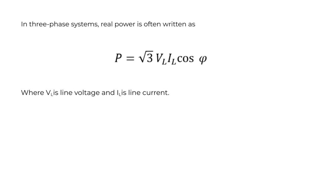
The idea of PF is the same in both systems. But three-phase systems are where PF correction is most common. That is because industrial loads are often motor-heavy. And the costs are higher.
This equation shows again why PF matters. For the same power, a lower resistance requires a higher current.
That current increase affects cable sizing, voltage drop, and transformer selection.
kW vs kVA in Generator and Transformer Sizing
Many people see a generator rated in kVA and wonder why. The reason is current and heating. A generator’s windings and alternator are limited by current.
How Utilities Treat Power Factor (Why Penalties Happen)
In many places, residential users are billed mainly in kWh. Power factor is not directly charged. But industrial and commercial customers may be billed based on kVA demand, kW demand, or have PF penalty clauses. Utilities care about current. Low PF forces them to supply more current for the same kW. That increases losses in their system. It also reduces capacity for other customers. So utilities encourage PF correction. That is why large plants install capacitor banks and PF controllers. Even if your audience is not dealing with utility billing yet, this explanation makes the power factor feel relevant and real.
How to Improve Power Factor (Practical Options)
Improving power factor usually means reducing reactive power demand seen by the source.
The most common method is capacitor banks. They supply reactive power locally. That reduces reactive current from the grid. Other methods include synchronous condensers and active power factor correction in power electronics. But capacitor banks are the most common in general electrical installations.
A simple practical principle is:
Correct PF near the load when possible. That reduces current in upstream cables. It reduces losses and voltage drop along the path.
Capacitor Banks: What They Actually Do?
Capacitors do not “create” real power. They do not reduce the kW required by the load. They reduce reactive power flowing from the supply.
This is important.
After PF correction:
- kW stays roughly the same (useful power is still needed)
- kVAR from the grid reduces
- kVA reduces
- current reduces
That is why cable heating can drop after correction. That is why voltage stability improves. That is why transformer capacity becomes available.
Common Power Factor Misunderstandings
Many people think PF correction saves huge energy. It can save some energy by reducing losses, but the main benefit is capacity and system performance. Another misunderstanding is thinking that PF is always a constant number. It is not. PF changes with load. Motors often have poor PF at light load. PF improves as the load increases. That is why correction systems sometimes use automatic capacitor steps. Another common mistake is over-correcting. Too much capacitance can cause leading PF. It can also cause resonance issues with harmonics. Correction should be done with proper sizing and sometimes with harmonic filters.
Power Factor and Harmonics (Short, Useful Note)
Some loads draw non-sinusoidal current. Examples include rectifiers, LED drivers, and VFDs. In these cases, there are two “factors” at play:
- displacement PF (phase shift)
- distortion PF (harmonic shape)
Many meters display true power factor. Some show only displacement PF. This can confuse users. If you work with modern electronics, use a meter that reports true power and true PF. That gives you reliable data. This is a deeper topic, but it is worth a short mention in a power factor explained guide.
Quick Rules of Thumb That Actually Help
Power factor becomes easier when you use a few practical rules.
If PF drops, current rises for the same kW. That is always true.
Motors and transformers usually have lagging PF. That is typical.
Capacitors improve lagging PF by reducing reactive current from the source.
kW is useful work. kVA is what the supply must handle. kVAR is the “field” part that supports inductive loads.
These simple rules are enough to understand most real situations.
Final Summary
Power factor describes how effectively AC power is converted into useful work. It connects kW, kVA, and kVAR in a simple relationship.
- kW is real power that does useful work.
- kVA is the apparent power that the source must deliver.
- kVAR is reactive power that supports fields but does not do real work.
Power factor is:
power factor = kW / kVA = cos θ
Low PF increases kVA and current for the same kW. That increases losses, voltage drop, and equipment loading. That is why PF correction is used, especially in industrial systems. Capacitor banks reduce reactive power demand from the source. They reduce current. They improve system performance. If you understand these points, you understand the heart of power factor explained.