If you are new to electrical and electronics engineering, this topic shows up everywhere. It appears in DC circuit lessons. It appears in basic wiring. It appears in troubleshooting. And it appears in real products around you. Many learners ask the same question. What is the series vs parallel circuits difference? The answer is simple once you see the pattern. Series circuits share the same current. Parallel circuits share the same voltage. Everything else flows from that. This guide explains both types clearly. It uses short sentences when needed. It also uses real-life examples, so the idea stays in your mind.
What Is a Circuit?
A circuit is a closed path for current to flow. It has a source. It has a load. It has conductors. The source provides voltage. The load uses electrical power. The conductors connect everything.
When we talk about series or parallel, we talk about how components are connected. The connection changes how current and voltage behave. That is why the wiring style matters.
Series vs Parallel Circuits Difference (One-Line Rule)
Here is the quickest way to remember it.
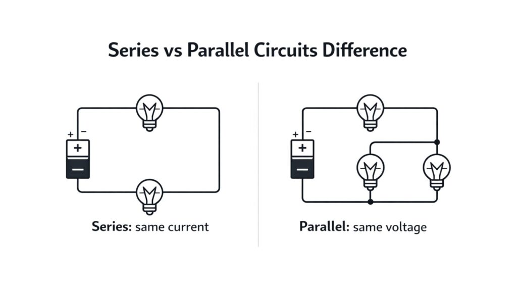
- In a series circuit, the same current flows through every component.
- In a parallel circuit, the same voltage appears across every branch.
That is the core series vs parallel circuits difference. If you understand that, you can solve most beginner problems.
Series Circuit Explained (Simple and Clear)
In a series connection, components are connected end-to-end. There is only one path for the current. Current has no choice. It must pass through each component one after another. Because there is only one path, the current is the same everywhere in the loop. It does not split. It cannot split.
Voltage behaves differently. The source voltage is shared among components. Each component gets a part of the total voltage. The sum of the voltage drops equals the source voltage. A series is often used when you want the same current through components. It is also used when you want to create a higher total resistance from smaller resistors.
Real Life Examples of Series Circuits
Series circuits exist in real products. But they are not as common as parallel circuits in building wiring. That is because series has one big weakness. If one component opens, everything stops.
A classic example is old-style Christmas lights. Many strings used series wiring. If one bulb failed, the whole string went dark. Some modern strings include shunt paths to reduce this problem, but the basic idea is still known.
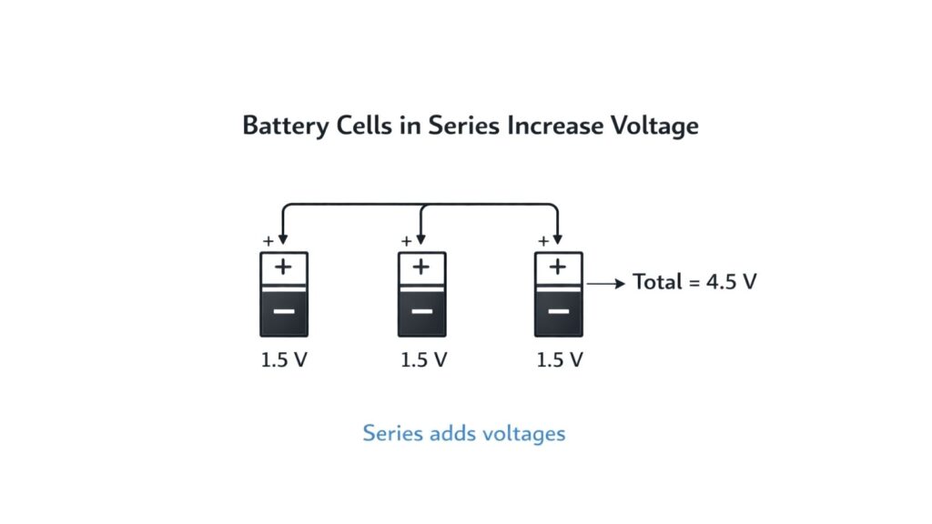
Another example is cells in a battery pack. Many battery packs place cells in series to increase voltage. For example, two 1.5 V cells in series produce about 3 V. Lithium-ion cells are often stacked in series for higher voltage tools and laptops.
A third example is a simple flashlight circuit. Many flashlights place batteries in series to increase voltage. Then the bulb or LED driver uses that voltage.
Series wiring also appears in protection devices. A fuse is placed in series with a load. A switch is also placed in series. If the switch opens, the current stops. That is the point.
What Happens If One Component Fails in Series?
This is where series circuits become easy to understand. If one component fails open, the path is broken. Current becomes zero everywhere. All loads stop working. This can be good for safety. It can be bad for reliability. That is why you do not wire household lamps in series. One lamp failure would turn off the entire house circuit. That would be unacceptable.
Parallel Circuit Explained (Simple and Clear)
In a parallel connection, components are connected across the same two nodes. That creates branches. Current has multiple paths. Because both ends of each branch connect to the same two nodes, the voltage across each branch is the same. Every branch “sees” the same supply voltage. Current behaves differently. Current splits among branches. Each branch draws the current it needs based on its resistance or impedance. The source supplies the total current, which is the sum of all branch currents. Parallel is used when you want loads to operate independently. It is also used when you want the same voltage across loads.
Real Life Examples of Parallel Circuits
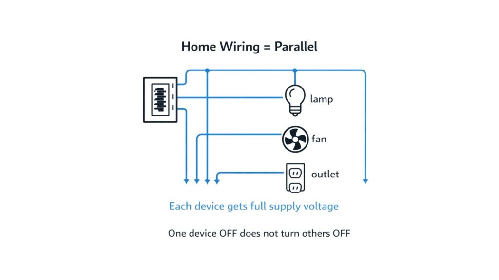
Parallel circuits are everywhere in real life. Your home wiring is the best example. Lamps, outlets, fans, and appliances are connected in parallel. That is why each device gets the full supply voltage. That is also why one lamp turning off does not turn off others.
Street lighting circuits are often arranged in a way that gives lamps independent operation. The aim is the same. A failure should not black out an entire area.
Inside electronic devices, many parts are connected in parallel, too. A phone has many circuits that share the same battery voltage through regulators. Each subsystem draws current as needed.
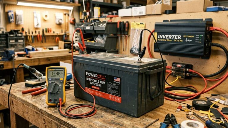
Car accessories are another example. The car battery provides about 12 V. Lights, radio, and other loads are connected, so each gets the same voltage. They do not need to be in series.
What Happens If One Component Fails in Parallel?
This is where parallel circuits shine.
If one branch fails open, the other branches still work. The circuit still has other paths. The supply still feeds them. If one branch fails short, that is dangerous. It can draw very high current. That is why fuses and breakers are essential. Protection is part of parallel system design.
So parallel gives independence. But it also requires good protection and correct cable sizing.
Series vs Parallel Circuits: Difference in Terms of Current and Voltage
Let’s lock the idea in with a simple comparison.
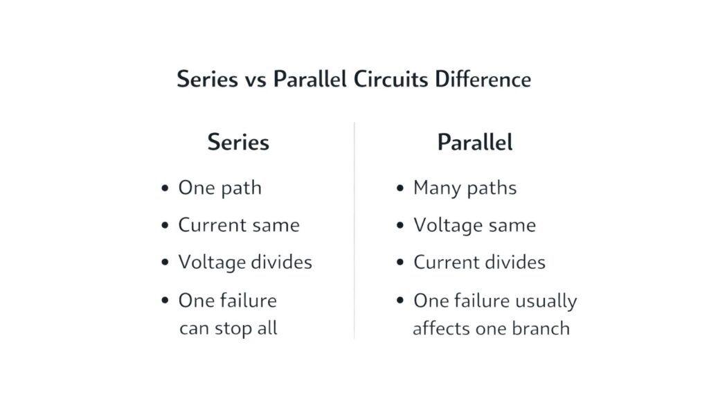
- In a series, the current is the same. Voltage divides.
- In parallel, the voltage is the same. Current divides.
That is the cleanest summary of the series vs parallel circuits difference.
How Total Resistance Changes in Series and Parallel?
This is another key difference. It matters in calculations and design.
Total resistance in series
When resistors are in series, resistances add. So total resistance increases. This is why a series is used when you want a larger resistance. It is simple and predictable.
Total resistance in parallel
When resistors are in parallel, total resistance decreases. Adding more parallel branches gives more current paths. So the overall resistance becomes smaller than the smallest branch resistance.
This explains why adding devices to a parallel circuit increases total current draw. It also explains why protection devices must be rated correctly.
A Practical Example You Can Feel (Two Lamps)
Imagine two identical lamps rated for the same voltage.
If you connect them in series to a supply, each lamp gets less voltage. They will be dim. The total brightness is lower.
If you connect them in parallel, each lamp gets the full voltage. They glow normally. Turning one off does not affect the other.
This simple example shows why home wiring uses parallel. It is about the correct voltage at each device.
Which Connection Is Better?
This is a common question. But the best answer is: it depends on the goal.
Series is useful when you need a higher voltage or when you want the same current through components. It is common inside battery packs and sensor chains. Parallel is useful when you want devices to work independently and see the same voltage. It is common in building wiring and distribution. So the “better” method is the one that matches your requirement.
Practical Rule for Troubleshooting
Troubleshooting becomes easier when you recognize series and parallel patterns.
If a whole section is dead, suspect a series break. That can be a blown fuse, open switch, broken connector, or failed wire. If only one device is dead, suspect a branch issue in a parallel system. That can be a bad socket, a broken lead, or the device itself. This simple thinking saves a lot of time in real work.
Common Mistakes Students Make
Many students mix up what is shared.
- They think voltage is the same in series. It is not. Voltage splits.
- They think the current is the same in parallel. It is not. Current splits.
Another mistake is assuming the total resistance formula without thinking. The series increases resistance. Parallel decreases resistance.
Students also forget to apply safety logic. Parallel systems need proper protection because a short-circuit branch can draw a huge current. If you remember the basic rule, these mistakes reduce.
Series and Parallel in Real Systems (Combination Circuits)
Most real circuits are not purely series or purely parallel. They are combinations.
A power strip is a parallel system. But the switch and fuse are in series with the strip. That is a series element in a parallel system. A home panel feeds many parallel branch circuits. But the main breaker is in series with the whole supply. Again, series and parallel exist together.
In electronics, you often see resistors in series and parallel to build a target resistance. You also see series parts used for current limiting. And you see parallel parts used for redundancy or current sharing.
Understanding the series vs parallel circuits difference helps you read these combined circuits faster.
Final Summary
The series vs parallel circuits difference can be understood with two simple rules.
In a series circuit, the same current flows through every component. Voltage divides across components.
In a parallel circuit, the same voltage appears across every branch. Current divides among branches.
Series is common in battery packs, switches, and protection paths. Parallel is common in home wiring and systems where devices must operate independently. Once you know what is shared, the rest becomes much easier. You will solve questions faster. You will wire circuits with more confidence. And you will troubleshoot with clear logic.